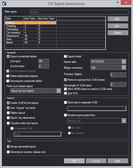
| Filter Name | The name of the filter |
|---|---|
| Style | (Read-only) Displays the style for an association. In the exported CFF2 file, all objects of the listed styles are associated with their respective line types. |
| Line type | (Read-only) Displays the line type associated with a style during export. During import, all objects with line types in the range are associated with the EngView style in the respective row. |
| Aux line type | (Read-only) Displays the auxiliary line type associated with a style during export. |
| Add | Opens a dialog box in which you create a new associations filter. |
| Edit | Opens a dialog box in which you edit the selected associations filter. |
| Delete | Deletes the selected filter. NOTE: You cannot delete the Default filter. |
| General | |
| Export unmatched | Sets how styles not present
in the list will be exported. For these styles, set line type
and auxiliary line type values according to the CFF standard.
|
| Line thickness in points | When the check box is selected, point is used as measurement unit for the thickness of the lines in the exported structure. |
| Delete duplicated objects | In exporting individual
parts, deletes all overlapping objects, leaving a single object.
Overlapping objects in adjoining parts are not deleted. USAGE
NOTE: The functionality is best applicable in exporting:
|
| Decompose composite styles | After the drawing
has been exported, objects in composite styles are broken
down to discrete elements. These elements take the properties
of the style set in the Structure tab of the original composite
style.
IMPORTANT: If the check box is left empty, after export the objects will have the line width set in the Production tab of the original composite style; their color and pattern will be those set in the Visual tab. Learn about the structure of composite styles. |
| Perfo/Cut-Crease Object | After the drawing
has been exported, objects in the CutCrease and Perforating
styles are broken down to discrete elements according to the
chosen criteria. The options:
|
| Export sheet | (1up and layout drawings) If the check box is selected, the program exports the sheet, if one has been defined. |
| Export side | Sets which side is exported. The options are:
|
| Bridge correction | Sets a rule about how to
proceed with correcting bridges during export. The options
are:
|
| Precision (digits) | )Sets how many digits there are to the right of the decimal separator for the numeral values in exported CFF2 files. |
| Remove spaces from SUB names | When the check box is selected, the program removes any spaces in the names of subroutines. |
| Max length of SUB name | Sets the highest number of symbols a subroutine name can have. |
| Allow MAIN name to match a SUB name | In the exported .cff file, the MAIN and the SUB will have the same name. |
| Unix EOL | When the check box is empty, the lines in the exported file end with two symbols: for a new line and for a carriage return. When the check box is selected, the lines end only with the symbol for a new line. |
| Layout | |
| Create subroutine for the layout | All objects in the layout other than the layout 1ups are exported in a different SUB in the CFF's file's structure. Such objects may be, for example, texts, dimension lines or measure lines. |
| Use "Layout" as name | After the export, both 1up and layout drawings have the name 'Layout'. |
| Flatten layout | (layout drawings only) When exported, all layout 1ups are broken down to discrete objects. |
| Export 1up dimensions | (layout drawing only) All measure lines in the 1up drawing are exported as objects and will be visualized in the layout drawing. |
| Transfer nicks into layout | Copies the nicks from bridges drawings into the exported layout drawings. There, they are indicated, and are listed in the exported file's routine. |
| In separate SUB | The program places the nicks in a separate subroutine in the exported file. In the box, type a name for the subroutine drawing as you want it to appear in the file. |
| Each part in separate SUB | Exports each layout part in its own SUB (drawing). Learn more about this functionality. |
| Number layout parts from | Sets a pattern for
how the program will number the layout array's parts in the
exported file. In the drop-down list, select a starting point
for the exported array: Bottom-Left, Bottom-Right, Top-Left
or Top-Right. Then choose a pattern that will array the parts
based on the starting point:
See an example of how layout parts are arrayed when the Bottom-Left starting point is used. |
| 1up | |
| Always Generate Layout | If the check box is selected, the objects in the 1up drawing are exported in a separate SUB, from which a layout drawing is generated regardless if there is one originally. |
| Dimensions numeric values only | (Applies for setting up the export of dimensions) When the check box is selected, only the values of dimension lines will be exported but no letters accompanying them. If there is at least one drawing with no scaling factor set, Scale to becomes available to allow you to select a scaling option. If the text Applied to nonscaled drawings appears, the scaling will be applied only to the drawings with no scaling factor. This will not override previously defined values. |
Create/Edit Association
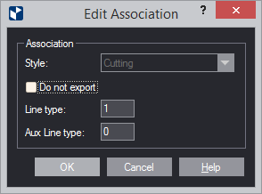
| Style | Sets the EngView style with which a line type will be associated in the CFF file during export. |
|---|---|
| Line Type | |
| Do not export | Objects in the selected style will not be exported. |
| Line type | Sets the line type to be associated with the style. In the export CFF2 file, all objects with the selected style are assigned the set line type. |
| Aux Line type | Sets the auxiliary line type to be associated with the style. In the export CFF2 file, all objects with the selected style are assigned the set auxiliary line type. |