Tool filters automate the association of the objects in the CAM drawing with the CAM tools that are in the CAM template. The associations are based on the general object attributes, such as, among others, type (line, arc, and so on), style, color, line or curve pattern. Each time you generate a tool path, you can choose whether or not to use tool filters.
Tool filters are specific for the CAM template to which they belong. You can access the tool filters from the ToolFilters tab in the tabular area of the CAM drawing. In the table, the arrangement of the tool filters corresponds to the order of association of the objects in the CAM drawing. (This is relevant when you have two or more filters whose objects have similar or identical attributes.) In the table, you can move a tool filter up or down via the commands in the context menu in the ToolFilters tab.
To create/edit a tool filter
NOTE: To see the tabular area if it is hidden, on the View menu, click Show tables.
The New Tool Filter dialog box appears.
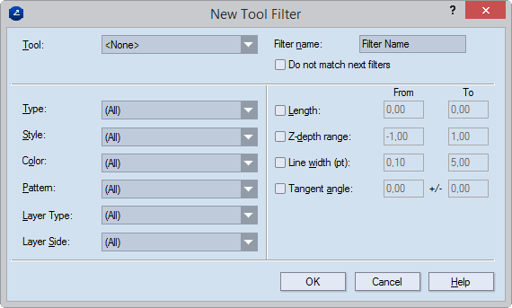
| Filter name | The name of the tool filter. |
|---|---|
| Do not match next filters | Stops searching through the settings of other filters after a match has been found. |
| Tool | The CAM tool with which the filter will associate all the objects with the attributes set for the filter. This list contains all the CAM tools available in the currently loaded template. |
| Type | The type of tool-filtered objects — point, line, arc, Bézier curve: all objects of the specified type (together with all other attributes) will be associated with the selected CAM tool. |
| Style | Sets the style of tool-filtered objects: all objects with the specified style (together with all other attributes) will be associated with the selected CAM tool. |
| Color | Sets the color of tool-filtered objects: all objects with the specified color (together with all other attributes) will be associated with the selected CAM tool. |
| Pattern | Sets the pattern of the constructional lines or curves of tool-filtered objects: all objects with the specified pattern (together with all other attributes) will be associated with the selected CAM tool. |
| Layer Type | Select the type of layer — Structural Design, Varnishing, Auxiliary or other — to which you want to apply the filter. |
| Layer Side | Select on which side (front, rear) of the layer you want to apply the filter. |
| Length | Sets the length range of the constructional lines or curves of tool-filtered objects: all objects that are in the specified length range (together with all other attributes) will be associated with the selected CAM tool. |
| Z-depth | Sets the stack order of a style. Value range: [–1 to 1]. If multiple objects in different styles overlap, the object in the style with the greatest stack order is visible on the screen and the others are not visible regardless of when each object was drawn. Example: If the Cutting style has a stack order of 0.5 and the Axis style has a stack order of –0.4, when objects in the two styles overlap, the one in the Cutting style will always be visible and that in the Axis style will always be not visible. |
| Line width (pt) | Sets the line width range of the constructional lines or curves of tool-filtered objects: all objects that fall into the specified range (together with all other attributes) will be associated with the selected CAM tool. |
| Tangent Angle | Sets the tangent angle range of the constructional curves of tool-filtered objects: all objects that fall into the specified range (together with all other attributes) will be associated with the selected CAM tool. |