The easiest way to create print presentations is to use design frames. In this video presentation, we use a predefined EngView design frame to prepare a printout of the 1up and layout drafted in Drafting a 1up from scratch and Creating a layout of a user-created 1up.
For detailed descriptions of the types, syntax and functions of the predefined formulas used in design frames, see the topic Formulas in design frames.
Nähere Beschreibungen der Typen, des Syntax und der Funktionen der in den Zeichnungsrahmen benutzten vordefinierten Formeln erhalten Sie in Formeln in Zeichnungsrahmen.
Visual: Creating printout presentations using EngView design frames
![]() Click the icon to watch the video. Run time: 3:00 min.
Click the icon to watch the video. Run time: 3:00 min.
PROCEDURAL STEPS
 .
.The Print Frame Placement page of the design frame wizard appears (the Select Print Frame step).
The Edit Design Frame page of the design frame wizard appears (the Setup Print Frame step).
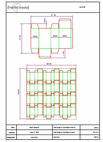
The design frame we opened has two predefined rectangle areas for parts to be inserted: OneUp1 and Layout. In these areas you can place any of the existing drawings; the existing drawings are listed in the OneUp column. To change the drawing that is to be inserted in a particular predefined area, click the right end of the OneUp column field for the respective area, select the drawing that you want, and then click Apply.
You can always edit design frame properties later: rest the pointer over the design frame to highlight it, right-click, and then click Object Properties on the context menu. Then in the dialog box that appears, edit the settings.
NOTE: To show dimensions, in the graphical area, right-click in an empty space, and then click Show Dimensions on the context menu.