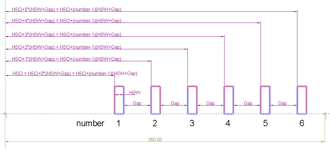
Pic. 1: All the components are visible, because N has the highest value it is allowed to take.
Multiple compound components have a finite number of individual components. When we use a multiple compound component in a resizable structure, we use a parameter (N) to define the number of individual components that we want visible. The highest value of N is the total number of individual components attached in the multiple compound component.
When we set the maximum value for N — that is, the total number — all individual components are visible (Pic. 1):

Pic. 1: All the components are visible, because N has the highest value it is allowed to take.
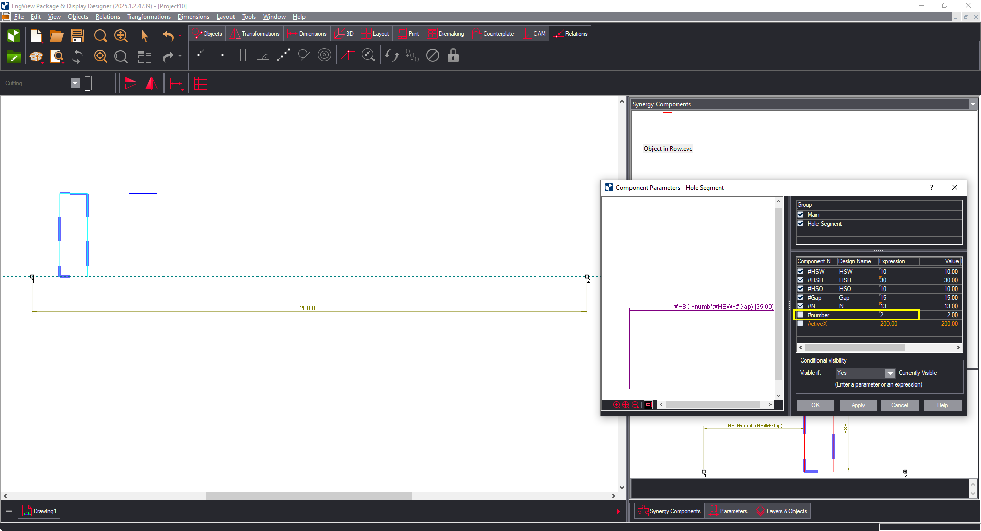
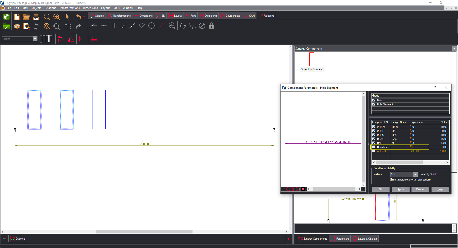
When in the compound component we set a value for N that is smaller than the maximum value — that is, fewer individual components than the total number — the individual components that make up the difference to the total number are positioned over the first one (Pic. 2):

Pic. 2: When N has a value lower than the allowed highest, the affected components are stacked onto the first component.
To create a multiple compound component, we use a single individual component. This component must have parameters for multiplying:

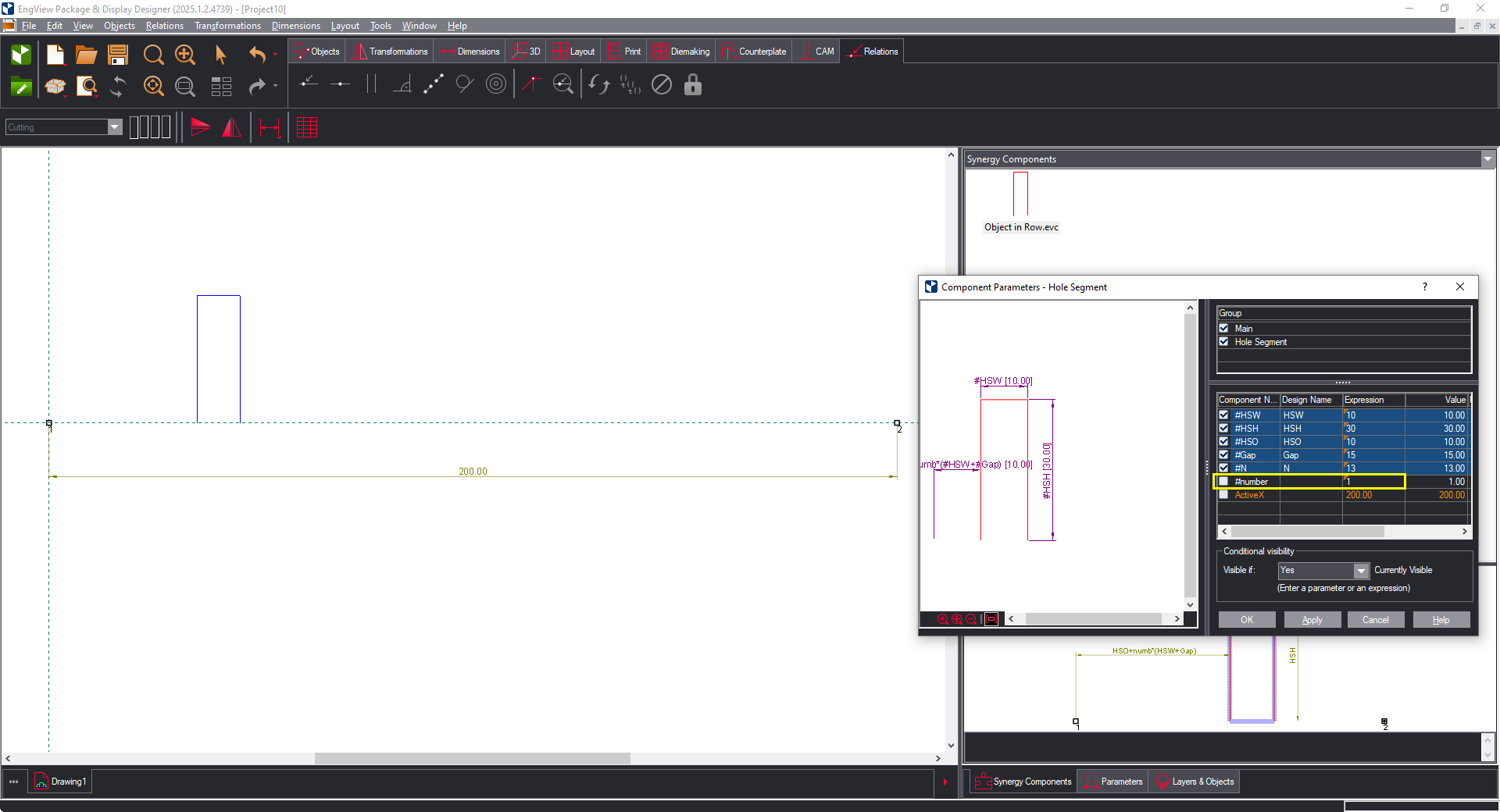
Pic. 3: Highlighted in yellows are the parameters that determine the offset of the individual component.
The parameters:
| HSO | Offset of the first individual component |
|---|---|
| Gap | Distance between the components. |
| N | Total (highest) number of objects that must be attached in the compound component. |
| number | Current (attached) number of the attached individual component. |
| numb | Real calculated number of the attached individual component. |
The formula that offsets each individual component is HSO+(number-1)*(HSW+GAP), but it applies for the individual components whose attached number (number) is lower than the total number (N):

Pic. 4: The general formula for offsetting the components
What do we do with the individual components whose attached number (number) is greater than the total number (N)?
In our case, we have attached 13 individual components, but we need to view only 10 of them. That is, we want to position the last three components – the ones with attached numbers 11, 12 and 13 – onto the first component (see Pic. 2).
To do this, we use the numb parameter. Its value is calculated according to the formula:
The parameter numb is the real calculated number of the attached individual component. This number takes part in the calculation of the actual offset of the individual component:
In this case, when N=10, the actual number (numb) of objects with an attached number (number) = 11, 12, 13 will become zero, because of the function iif(N-number>=0; number-1; 0).
In fact, the last three individual components (those with numbers 11, 12, 13) will be positioned over the first one, because of the HSO+numb(HSW+Gap)=HSO+0*(HSW+Gap) = HSO formula.
NOTE: The numb parameter must be a Local parameter.
IMPORTANT: All objects in the individual component must have overlapping flags.
The IIF function has the following pattern
The function determines whether an expression is true or false. If the expression is true, the function returns the truepart value; if it is false, the function returns the falsepart value.
TIP: The default distance between the two control points is 50.80 mm (2 inches). You can choose to make it bigger, for example 200 mm.

Pic. 5: Attaching the component for the first time.

Pic. 6: Attaching the component for the second time.

Pic. 7: Attaching the component for the third time.

Pic. 8: Making the parameters Global and assigning the highest number they can be.

Pic. 9: The AX1 parameter goes to the topmost position in the parameter list.

Pic. 10: Making the HSOcalc parameter Local.

Pic. 11: Creating the HSO parameter and making it Global.

Pic. 12: Entering the formula that calculates the hole segment offset.
Now when N=1, the hole segment will be in the middle — that is, EngView will not consider HSO and will compute (AX1-HSW)/2, which will position the hole segment in the middle:

Pic. 13: Centering the hole segment.
If there is no formula for the Gap parameter, when N>1 the parts will not be centered according the active points:

Pic. 14: The components are not centered, because Gap has not been determined by a formula.
To calculate the GAP automatically

Pic. 15: The Gap is now Local and is below the HSOcalc parameter.

Pic. 16: Gap as calculated by its formula.