Applying checkbox symbols: examples
In the graphical area, double-click the symbol.
In the graphical area, right-click the symbol, and then click Objects Properties.
In the tabular area, in the Layers & Objects tab, in the Type column right-click the symbol's icon, and then click Properties.
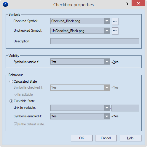
The Checklist Symbols dialog box appears.
Symbols In this
group, you set the images that will indicate the checked and unchecked
states of the symbols. You also add a description for what the symbol
stand for. NOTE: The images are located in the EngViewWork7\Settings\ControlsSymbols
folder of your installation. If you want to add an image other than the
available, click the browse button  and load the new image. It is then automatically copied to the default
directory and will later appear in the drop-down list.
and load the new image. It is then automatically copied to the default
directory and will later appear in the drop-down list.
Checked symbol In the drop-down list, select the image that you want to indicate the checked state of the symbol.
Unchecked symbol In the drop-down list, select the image that you want to indicate the not-checked state of the symbol.
Description Type a brief note about what the symbol stands for. In print drawings, this text will appear in the tabular area (in the Type column of the Design Frame tab).
Visibility In this group, you set the condition that defines when the symbol will be visible in print drawings. When the set condition is met, the symbol is visible.
Symbol is visible if Set a condition of how to make a symbol visible. NOTE: Even if the symbol is set to be invisible in print drawings, it is always visible in the design frame.
Behaviour Settings about whether the symbol will be available (clickable) in a print drawing
Calculated state Sets the symbol as nonclickable in print drawings. The concrete state (checked or unchecked) is defined automatically by the condition set in Symbol is checked if.
Symbol is checked if Set a condition of how to make a symbol checked.
Is editable (design frame only) Select this check box to enable editing the condition of how to make the symbol checked when you are working in print drawings. NOTE: This editing takes place in the tabular area — in the Data column of the Design Frame tab.
Clickable State Sets the symbol as clickable in print drawings. When a symbol is clickable, its state can be changed by hand.
Link to variable This property sets an variable for the symbol. It extracts the current state of the symbol — checked or not checked. The checked state returns the value 1; the unchecked state the value 0 (zero). You can use this variable while creating the conditions for other symbols (see example 1 below), or it can be used in design frame formulas (see example 2 below).
The property consists of two members — the first is optional and is the drawing where the variable is saved. If no reference to a drawing is made, the variable is local and can be used only in the current design frame. If a reference is made to a drawing that will contain this variable, it can be used also by other design frames in the same project.
The second member is a name of a variable.
TO DEFINE A VARIABLE:
The first member Type the name of the drawing in which you want to store the variable of the symbol — for example, OneUp1. IMPORTANT: If you will not use the state of the symbol (the variable) in other design frames, leave this member empty.
The second member Type а name of a variable with which you want to associate the symbol — for example, HasVarnish.
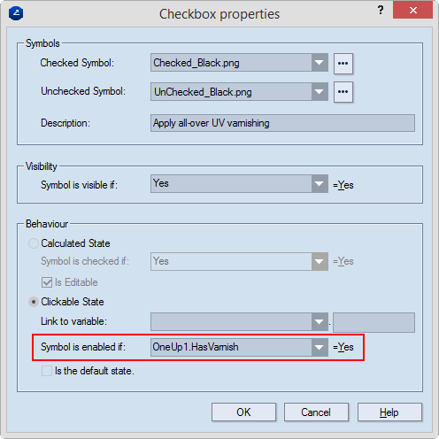
Symbol is enabled if Set a condition of how to make a symbol enabled.
Is the default state (design frame only) Select the check box to load a default state for the symbol — checked. Later, while working in a print drawing, you can change the state.
Consider the following examples of how to define and use variables for setting the behavior of checklist symbols:
The example describes how to create a varnishing process-related symbols. A design frame contains three symbols related to UV varnishing processes: a main symbol (linked to the OneUp1.HasVarnish variable) that indicates whether UV varnishing has been applied, and two second-level symbols that describe the varnishing processes All-over UV and Spot UV. The second-level symbols become available ONLY WHEN the first symbol is in the checked state.
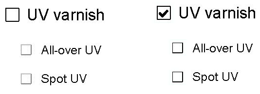
The state of the smaller, greyed check boxes depend on the state of the larger ones. They are disabled, left, because the UV varnish symbol is unchecked; they are enabled for checking, right, because the UV varnish check box is checked.
To define the ONEUP1.HASVARNISH variable
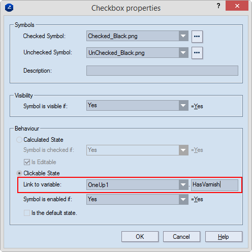
The variable OneUp1.HasVarnish has been created. It will be saved in the drawing that corresponds to the OneUp1 predefined area when the design frame is put to use in a project.
Using variables for creating conditions for other symbols
The example contains a formula with which we will print out the cost of a varnishing process.
The variable OneUp1.HasVarnish indicates the state of the symbol — 0 (unchecked) or 1 (checked). If the symbol is unchecked (zero), the varnish cost is also zero.