 .
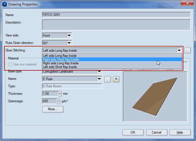
.The glue flap has two geometrical positions: to the left or to the right, on a long or on a short panel of the box. The positioning of glue flaps is set in the Drawing Properties dialog box.
To prepare a design
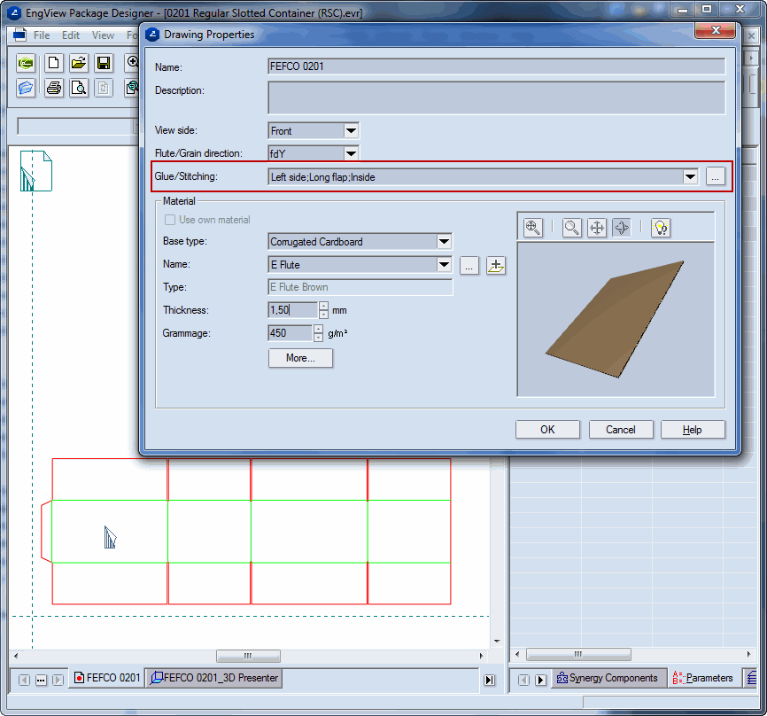
NOTE: For the purposes of the following example about how to set the side of the glue flap, the design FEFCO 0201 Regular Slotted Container (RSC).evr is used.
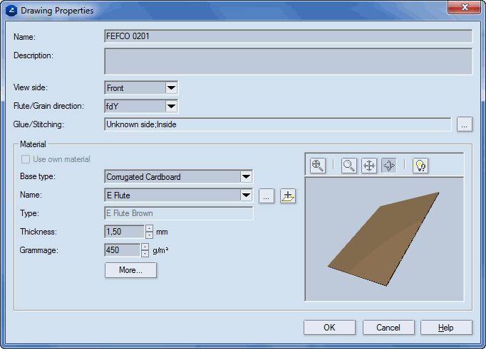
The Drawing Properties dialog appears.
 .
.The Manufacturing joints dialog box appears.
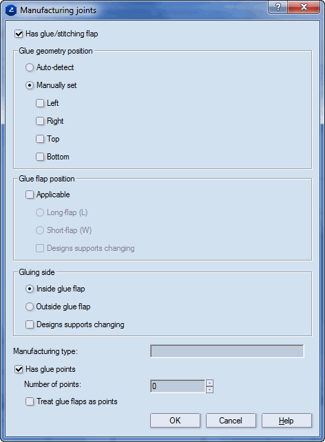
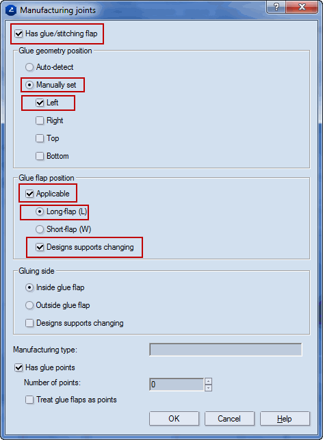
IMPORTANT: Note that the glue flap is on the left side of the design (this is set in the Glue geometry position area) and is attached to the long panel (this is set in the Glue flap position area).
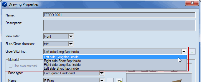
Note that in the Drawing Properties dialog the Glue/stitching drop-down list is now available and offers a list of glue flap positioning choices.
The Component Parameters dialog box appears.
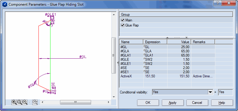
NOTE: We use the GLFLong() function because the selected glue flap is on the long panel.
NOTE: Because the new component is attached onto the short panel, the function that controls short panels is needed: GLFShort().
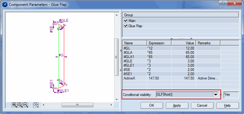
NOTE: The functions GLFLong() and GLFShort() cause the glue flaps to be visible or invisible, taking into account the settings in the glue flap position area in the Manufacturing joints dialog — see Step 4.
