 .
.You might need to see the measurements of a design in its 3D representation. When 3D models are exported as PDF files, also the measurement lines are exported and can be seen in the 3D PDF file.
You can place measurement lines between:
Measurement lines are applied to the step they are added in, and are listed, in the tabular area, as individual actions at the bottom of the step's list of actions.
To add measurement lines in a 3D representation
. .
.You are now in the mode for adding measure lines. Nothing has happened to the 3D view on the screen. Note the Hide in next step check box that appears in an edit bar above the 3D representation. Selecting the check box hides the measurement line in the next step of the folding sequence. You can work the check box any time along the procedure that follows.
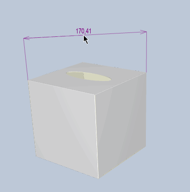
A measure line appears between the two points. Also the value of the distance is displayed.
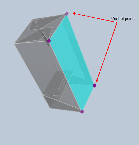
NOTE: You can click any control dots that you are seeing at the moment and which are indicated in violet.
TIP: To reach a distant point or one that is behind a panel, zoom into the 3D representation.
TIP: To change the position of the measure line, select the line, and then start moving it to where you want it to be.