The View Options dialog box appears.
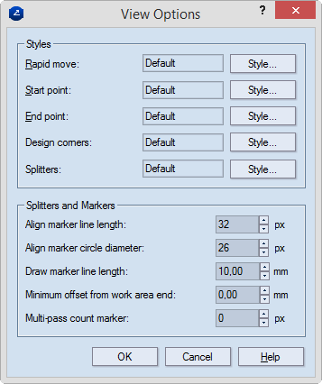
Styles Settings of the styles used for visualizing the elements of the CAM tool's movement. For all the items, to change the active style, click the respective Style button, and then select a new styles.
Rapid move Displays the style that is used for displaying the rapid moving ("jumping") of the CAM tool along the tool path.
Start point Displays the style that is used for displaying the starting point of the CAM tool in the tool path.
End point Displays the style that is used for displaying the end point of the CAM tool in the tool path.
Design corners Displays the style that is used for displaying the design corners during movement of the CAM tool in the tool path.
Splitters Displays the style that is used for displaying the splitters necessary for the CAM tool to correctly continue operating along the tool path.
Splitters and Markers Settings about how splitters and align markers are visualized on the screen
Align marker line length Sets the length of the line of the align markers. Value range: 0–100 pixels.
Align marker circle diameter Sets the diameter of the circles of the align markers. Value range: 0–100 pixels.
Draw marker line length Sets the length of the lines of the draw markers. Value range: 0–100 metric units.
Min offset from work area end Sets the minimal offset distance between the splitter and the end of the work area. In some cases, the splitter is set too close to the work area end, and the machine cannot work. Setting a proper offset resolves this issue. Also, the Draw marker length must be conformed with minimal offset, that is, it must not exceed the minimal offset; otherwise, the draw markers cannot fit within the area defined by the minimal offset. The number of simultaneously placed splitters depends on the minimal offset. Value range: 0–100 metric units.
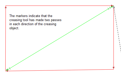
Multi-pass count marker Type how large (in pixels) you want to see the markers indicating how many times the tool has passed along a tool path section and in which direction. (You set this count while setting the CAM tool properties (in the Multiple passes check box). The markers appear at each end of the section indicating the direction. The default value is zero.
NOTE: The style Default means that no style is selected. Use it if you want to set a color to a certain object type without associating it with any style.
NOTE: You can use splitters to work with materials that are larger than the work area of the machine. Draw markers are real markers drawn on the sheet, in the work area of the machine. They are used as starting points. Align markers are virtual representations of the draw markers. Each time you move the material toward the work area, the align markers serve as guides for the operation, precluding an unacceptable offset.