 and blue dots
  , respectively. By default, they are positioned at the origin of the coordinate system.
The dialog box appears, with five tabs: Machine Settings, MCS and Alignment, Property Sets, Machine Custom Properties and Tools Custom Properties.
In this tab, after selecting a machine, you can edit it, define its NC script output file, set, add and delete custom properties, define machine visualization, as well as bridge orientation, roller support and splitter direction:
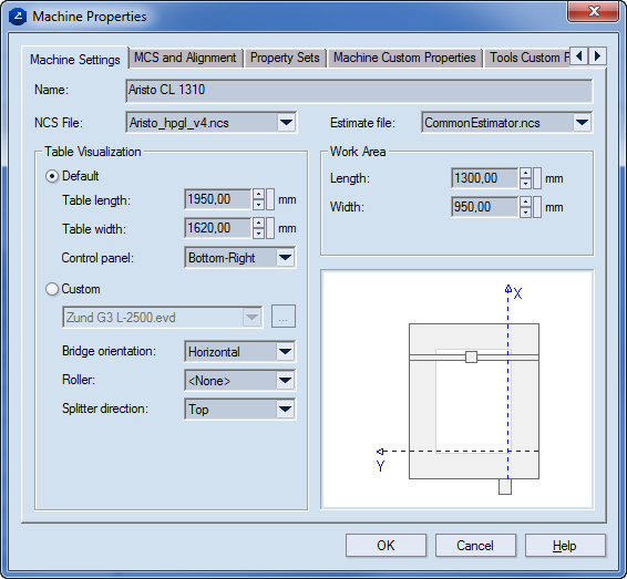
Name Sets the name of the current machine.
NCS File Determines the NC script (NCS) file to be used for the selected machine. To every machine an NC Script must be assigned.
There are several predefined NC scripts which are installed by default. They work for the most-commonly used CAM machines. For a script for a machine that is not included in the list of machines, contact Technical Support or write your own script. For details how, read the file ncscript_guide.txt in the Documentation sub-folder of your installation.
Estimate File Determines the file used for making a job estimation. Output data based on this file can be seen as information in the CAM toolbar's Job Estimation tab of the tabular area.
Table Visualization Settings pertaining to the visualization of the respective machine
Default To use the default visualization of the current machine, click this option. It corresponds to the size of each machine. The initial size is represented in Table Length, Table Width, Work Area Length and Width. Use these fields to set the dimensions of a new machine or edit the existing ones.
Table Length Sets the overall length of the table. Changes the visualization.
Table Width Sets the overall width of the table. Changes the visualization.
Control Panel Sets the position of the control panel on the current machine. From the list select from eight available positions.
Custom To use your own visualization, click this option. Click the Browse button, and in the dialog box that appears, locate your file to add it to the database. The newly added file can be worked on in the program and has to be saved as an EVD file.
Bridge Orientation Determines the orientation of the bridge, depending on the machine that you are using. Two options are available: Vertical and Horizontal. The bridge orientation affects the options (described bellow) available for the splitter direction and roller position.
Roller Sets whether the current machine has a roller or not. If it has a roller, you can define the roller's position depending on the bridge orientation. If the bridge orientation is 'Vertical', the roller position options are Right and Left. If it is 'Horizontal', the roller position options are Top and Bottom.
Splitter direction Sets the splitter direction of the current machine. Also dependable on the bridge orientation. If the bridge orientation is 'Vertical', the splitter direction options are Right and Left. If it is 'Horizontal', the splitter direction options are Top and Bottom.
Work Area Sets dimensions of the work area as part of the machine table
Length Sets the overall length of the work area on the machine table. Changes the visualization.
Width Sets the overall length of the work area on the machine table. Change the visualization.
In the MCS and Alignment tab you can set the default display and alignment settings for both coordinate system and design's bounding rectangle on the currently selected CAM machine.
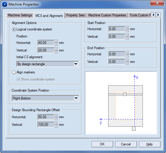
Alignment Options Options that pertain to the visualization of the currently used coordinate system, but not of the position of the coordinate system.
Logical Coordinate System If a machine with a logical coordinate system is used, the option must be selected.
Position Determines the position of the coordinate system axes in respect to the work area.
Hor Sets the horizontal offset of the design's bounding rectangle in respect to the work area borders. Depending on the coordinate system position, the offset may affect either coordinate axis: the offset is set to lie horizontally in respect to the nearest work area border, ignoring the coordinate system position.
Vert Sets the vertical offset of the design's bounding rectangle in respect to the work area borders. Depending on the coordinate system position, the offset may affect either coordinate axis: the offset is set to lie horizontally in respect to the nearest work area border, ignoring the coordinate system position.
Align by design origin When the check box is selected, the origin of the machine's coordinate system is aligned to that of the design. NOTE: The CAM drawing must be refreshed for the changes to take effect. IMPORTANT: If specific offsets are set for the machine's coordinate system in Hor or Vert, or both — it is they that apply.
Align Markers If you are using a machine with align markers, this option must be selected.
Show coordinate system Available when you use a machine with align markers. Displays the coordinate system in the graphical area.
Coordinate System Position Determines the coordinate system's position over the machine's work area. Four positions cover all possible cases.
Design Bounding Rectangle Offset Sets all options pertaining to the visualization of the bounding rectangle position regarding the work area.
Horizontal Sets a horizontal offset regarding the coordinate axes. Depending on the coordinate system position, the offset may derive from either axis, as it is set to always lie horizontally.
Vertical Sets a horizontal offset regarding the coordinate axes. Depending on the coordinate system position, the offset may derive from either axis, since it is set to always lie vertically.
Start & End Position Determines the position (visualization) of the start and end points, displayed on the screen as thick green and blue dots , respectively. By default, they are positioned at the origin of the coordinate system.
Start Position
Horizontal, Vertical Set the horizontal/vertical offset of the start point in respect to the coordinate axes, thus defining the start position of the generated tool path. Depending on the coordinate system position, the offsets may originate from either axis, as they are set to lay always in a horizontal, respectively, vertical direction.
End Position
Horizontal, Vertical Set the horizontal/vertical offset of the end point in respect to the coordinate axes, thus defining end position of the generated tool path. Depending on the coordinate system position, the offset may originate from either axis, as they are set to always lay in a horizontal, respectively, vertical direction.
In the Machine Custom Properties tab you can edit the settings for a particular machine. For example, if the current machine does not support arc manipulation, you can define a new option, decomposing all arcs into straight segments.
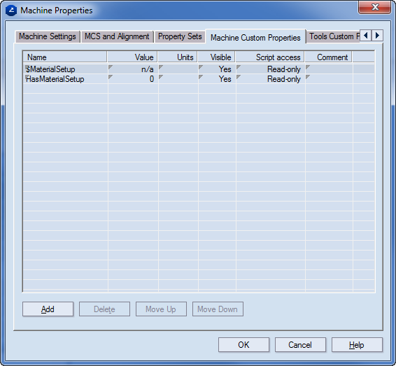
Name Displays the name of the machine custom property.
Value Sets the default value of the machine custom property.
Units Sets the default units.
Visible Displays the status of the machine's custom properties — Yes (visible) or Not (hidden).
Script access (Editable) Sets how the script will handle the tool's value setting. The options are:
Read-only The script uses the value of the property as it is defined by the CAM template, making no changes to it during the job.
Local Only During the job the script dynamically makes changes to the value of the property. When the job is completed, these changes are lost.
Committable During the job the script dynamically makes changes to the property value. When the job is completed, the changes are saved to the CAM template and are applied when the next job is started.
Comment A field for comments pertaining to any of the machine custom properties.
Add Creates a new property record.
Delete Removes the selected property record.
Move Up Moves the selected property record up one row.
Move Down Moves the selected property record down one row
In the Tools Custom Properties tab, you can create options pertaining to the tools that are present with each machine, as well as redefining the current tool settings.
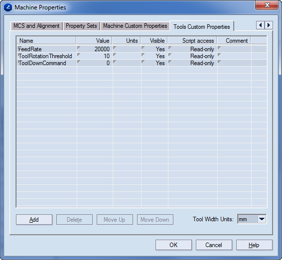
Name Displays the name of the tool custom property.
Value Sets the default value of the tool custom property.
Units Sets the default units.
Visible Displays the status — Yes or Not — of the tool's custom properties. Depending on the status, a tool custom property is either visible in the CAM Tools tab of the tabular area or not.
Script access (Editable) Sets how the script will handle the tool's value setting. The options are:
Read-only The script uses the value of the property as it is defined by the CAM template, making no changes to it during the job.
Local Only During the job the script dynamically makes changes to the value of the property, which are lost when the job is complete.
Committable During the job the script dynamically makes changes to the property value. When the job is completed, the changes are saved into the CAM template and are taken into account when the next job is started.
Comment A field for comments pertaining to the tool custom properties.
Add Creates a new property record.
Delete Removes the selected property record.
Move Up Moves the selected property record up one row.
Move Down Moves the selected property record down one row.