Scale groups are sets of print drawing parts to which a common scale factor is applied. The use of scale groups guarantees that, when printed out or seen on the screen, the drawings appear in proportion to each other. The functionality comes in handy especially for printing and viewing 1ups, layout drawings or 3D models of components of displays. (Normally in displays, some parts are much larger than others and would appear out of proportion on-screen or on paper if each part uses its own scale factor.) Applying universal scaling for parts that belong to structures made up of multiple, variously sized parts guarantees that all these parts appear — both on the screen and on paper — in proportion to one another.
EXAMPLE: A design frame has three rectangular areas with the Fit to rectangle option. When the design frame is used as the basis of a print drawing, if the three areas are not grouped, the program will compute three different scale factors for each of them — for example, 0.2, 0.6 and 0.8 — so that the respective drawings would fit in the rectangular areas. Because the parts have different overall dimensions, different scale factors will be computed for them when they are fitted into the rectangular areas. This will cause them to appear out of proportion to each other. So for drawings that belong to the same complex structure (a display or a body-and-lid box), it is best to put the three areas in a group and use the largest computed scaling — in this case, 0.2. This ensures that all the drawings appear in proportion to each other, thus giving a realistic idea of how the parts stay together.
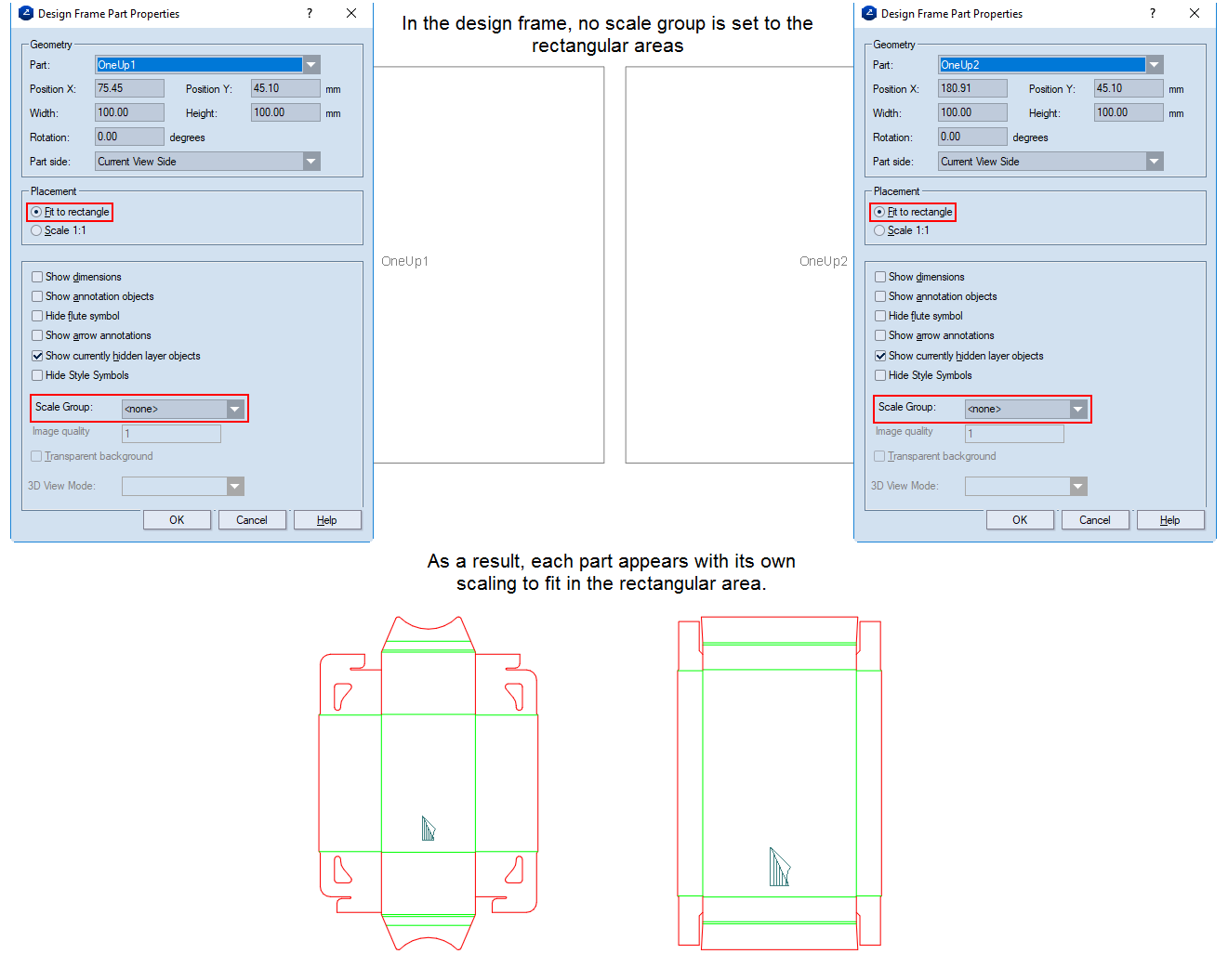
Consider the difference between scaling parts independently and after applying a scale group. NOTE: The example that follows uses two parts in the print drawing.
