Process Effects: Work environment
The technological work on process layers — that is, the space where they are created, edited and deleting — takes place in the 1up drawing. Visualization of the surface effects and choosing the process types are done in the 3D drawing.
Workspace in the 1up drawing
Process layers are created, edited and deleted in the 1up drawing and working with them takes place in the Layers & Objects tab in the tabular area. The tab is divided into two sections:
- Layers Lists the available process layers, their type and position.
- Objects Lists the objects contained in the process layer selected in the Layers section. If no process layer is selected in the Layers section, the objects contained in the entire design are listed.
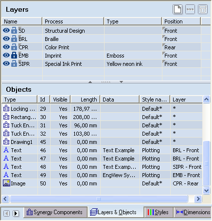
The Layers & Objects tab. No process layer is selected in the Layers section, and all the objects in the design are listed in the Objects section.
|
Style indication
|
What the icons mean
|
|
Visibility
|
 Indicates that the objects in this process are visible in the graphical area. Indicates that the objects in this process are visible in the graphical area.
|
|
 Indicates objects that the objects in this process are not visible in the graphical area. Indicates objects that the objects in this process are not visible in the graphical area.
|
|
Editablity
|
 Indicates that the objects in this processes can be edited — for example, you can delete them and edit their properties. Indicates that the objects in this processes can be edited — for example, you can delete them and edit their properties.
|
|
 Indicates that the objects in this processes cannot be edited: you cannot delete them or edit their properties. Indicates that the objects in this processes cannot be edited: you cannot delete them or edit their properties.
|
The Layers section
Name Indicates the name of the process: SD (structural), BRL (Braile), CPR (color print), EMB (Imprint), SIPR (special ink printing), LMN (lamination), VSH (varnishing), PFS (partial foil stamping), MRP (monochrome print), DB (dieboard), SH (sheet), AUX (auxiliary).
Process Displays the name of the process.
Type Indicates the type of the process layer. (This property is editable only in the 3D drawing.)
Position Indicates whether the process applies to the front or the rear side of the material. (This property is editable only in the 1up drawing.)
The Objects section
Type Shows what the objects is: drawing, image, text, line, circle, and so on.
Id System-generated number for the object.
Visible Indicates whether the object is visible in the graphical area. The options are Yes and No.
Length Displays the size of the object. NOTE: The information is context-dependent — for example, no quantifiable data is displayed for text and images.
Data Displays the content of the object. NOTE: The information is context-dependent — for example, no data is shown for geometric objects or images; for text the actual content of the text is displayed.
Style name Shows the style of the object. Default* means that no concrete style has been assigned to the object.
Layer Shows to which layer the object is assigned. The * symbol indicates that the object is a compound object whose components belong to various layers.
Workspace in the 3D drawing
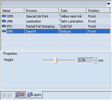
The Dropdown list In 3D representations with multiple 3D parts, lists the rest of the 3D parts. Only the process layers for one part are visible at a time.
Name Indicates the name of the process: SD (structural), BRL (Braile), CPR (color print), EMB (Imprint), SIPR (special ink printing), LMN (lamination), VSH (varnishing), PFS (partial foil stamping), MRP (monochrome print), DB (dieboard), SH (sheet), AUX (auxiliary).
Process Displays the name of the process.
Type Indicates the type of the process layer. (This property is editable only in the 3D drawing.)
Position Indicates whether the process applies to the front or the rear side of the material. (This property is editable only in the 1up drawing.)
Properties Context-specific settings for the surface process at hand.