Generating layout from displays in 3D
You can start producing a display or a series of the same display directly after you have agreed on its structure and design in 3D. You need only generate layouts of its components, send them to a cutter, and then assemble the cut components into actual displays. The entire process can begin directly from the 3D drawing.
NOTE: Layout can be generated only from designs that have more than one drawing.
To create layout of 3D drawings
- Do one of the following:
- On the , click New Layout Drawing
 .
.
- On the Layout menu, click New Layout Drawing.
- Press CTRL+L+N.
NOTE: The wizard can be started also from a 3D assembly drawing: On the , click Create Layout from 3D and the wizard will open directly. In this case, the nesting will apply for the active design displayed in the 3D drawing and will take into account its display components.
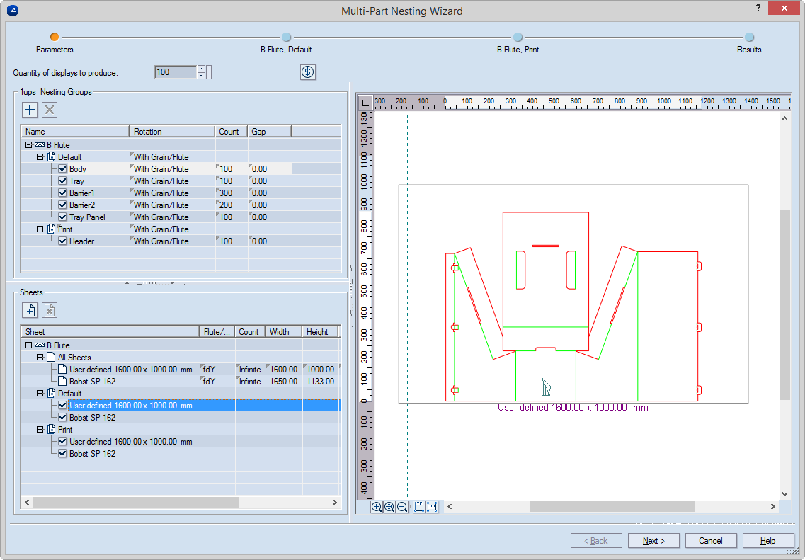
The Multi-Part Nesting Wizard opens at the Parameters page.
Quantity of displays to produce Sets the number of displays that you will want to produce.
Use bleed Select this check box if bleed will be applied to the 1ups.
 Cost Parameters Opens a dialog box in which you set the parameters used for calculating a cost estimate for the variant.
1up Nesting Groups Settings that define how the layout 1ups will be arranged on the sheet. NOTE: The 1up selected in the table is displayed in the preview area.
 Add/Remove Group buttons. The Plus button adds a group to the list to which parts can be placed that will be subjected to special treatments — for example, to which printed materials will be applied. The X button removes a selected group. NOTE: The Default group cannot be removed.
Name The name of the 1up as it is created in the project. If you do not want the 1up to take part in the layout, leave empty the check box in front of the name.
Rotation Sets an angle of rotation for the 1up during the filling of the sheet. This means that the program will rotate the particular 1up only at the angle you have specified. The options are:
Free Rotation The program tries various rotations until an optimal layout is achieved.
Increment The program populates the sheet by successively rotating the layout 1up by a step of either 90 or 180 degrees. For example, if you have selected 90 degrees Increment, to populate the sheet, the program will compute the optimal filling solution by making successive attempts, each time rotating the layout 1up at 90 degrees.
Fixed The program populates the sheet by keeping the 1up at a selected angle. For example, if you have selected 270 degrees Fixed, to populate the sheet, the program will compute a layout variant with the layout 1up rotated at 270 degrees.
With Grain Takes account of the grain or flute if a grain/flute direction has been set in Grain/Flute.
TIP: To set identical rotation to all the elements in a group, in the Default row, click the Rotation field. Then, in the dropdown list that appears, select the rotation that you need.
Count Sets how many layout 1ups will be created out of this 1up and will be featured in the layout.
Gap Sets a gap between the separate layout 1ups.
Sheets Lists the sheets of the selected material. NOTE: A record appears in this list when the respective sheets are added in the Sheet column in the table below. See how to do this in the next control description.
 Add/Remove Sheet buttons. The Plus button adds a sheet to the display layout. The X button removes a selected sheet.
Sheet Sets the sheets that will be used for the display layout. The sheets in the list appear in the Sheets column in the above table. NOTE: To add a sheet, right-click any row in the table, and then click the Plus button; then, from the list that appears, select a sheet. To delete a sheet, right-click it, and then click the X button.
Flute/Grain direction Sets if the sheet will take into account the grain or flute of the material. The options are: fdX (arranges the 1ups according to the horizontal grain (or flute) of the sheet); and fdY (arranges the 1ups according to the horizontal grain (or flute) of the sheet).
Count Sets the number of sheets available.
Width Sets the width of the sheet. Editing this setting causes the selected sheet to appear as User-defined in the tables above.
Height Sets the height of the sheet. Editing this setting causes the selected sheet to appear as User-defined in the tables above.
- Edit the settings as you need them to be, and then click Next.
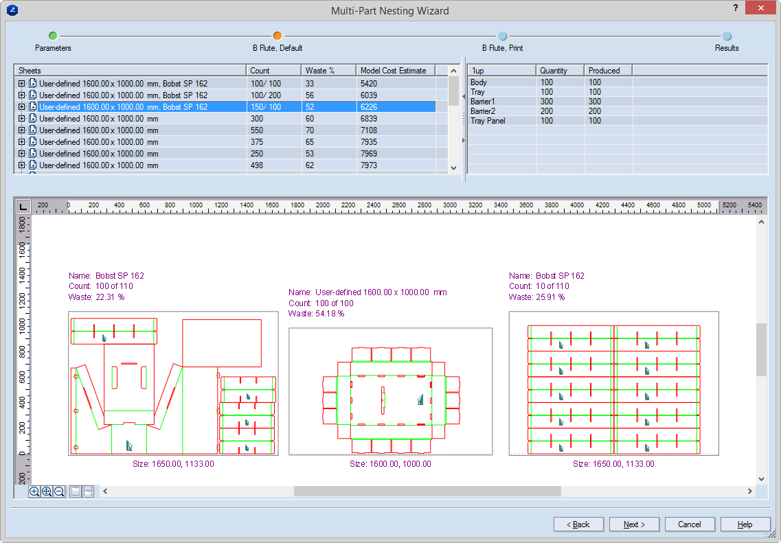
The next page of the wizard appears.
NOTE: The number of intermediate wizard steps between the steps Parameters and Results depends on the number of materials used for components in the display. As a result, a wizard will have as many intermediate pages as is the number of materials used in the display's components. In the wizard, each intermediate step is named after the material that the step deals with. For example, if all the components of a display are made of only one material, the wizard will appear with only one intermediate step; if two materials are used in the display, the intermediate step will be two, and so on.
Sheets A list of the sheets that the variant will require so that the set number of 1ups are produced
Count Displays how many units of the part will be produced.
Waste (%) The percentage of the total waste for the variant
Model Cost Estimate Displays the relative cost for the variant. Learn what this cost means and how it is calculated.
1up The name of the 1up
Quantity The number of 1ups that need to be produced (set in the Count column in the Parameters page (the right-hand table)).
Produced The number of actually produced pieces of the 1up. This number may turn out smaller than the one set originally (see the Quantity column).
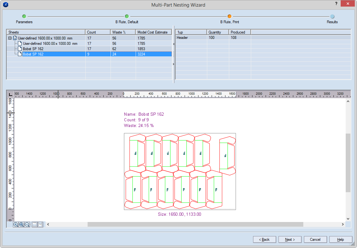
- Edit the settings as you need them to be, and then click Next.
NOTE: Depending on the number of materials used, the dialog box in Step 3 will appear for each material. See the note in Step 3. Here an example is shown about the parts that will carry the print work.
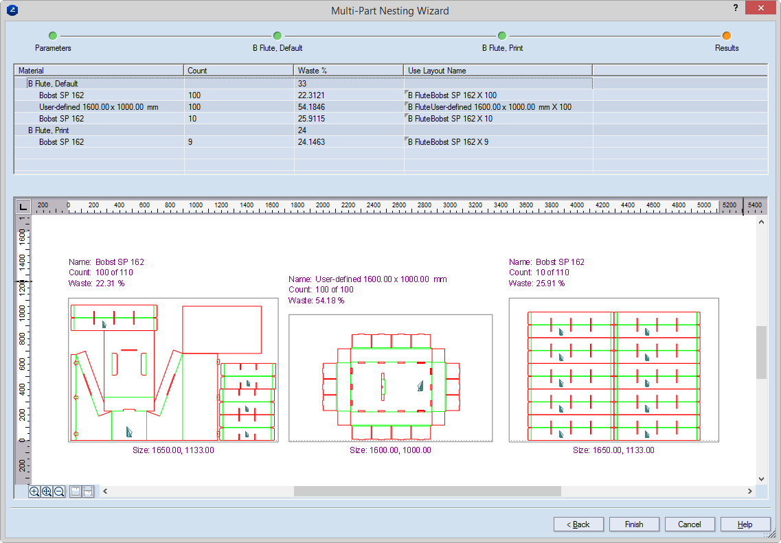
Material Displays the material used for the variant.
Count Displays how many sheets are needed for producing the set production run. That is, how many times the variant needs to be produced so that the production run can be assembled.
Waste % Displays the waste that the variant will produce.
Use Layout Name (editable) A name generated automatically from the name of the material, the name of the sheet, and the number of sheets needed for producing the parts in the selected layout. Example: The name B FluteBobst SP 162 X 100 reads: B Flute (material), Bobst 162 SP (sheet name), 100 (number of required sheets). Because after the layout is generated, this name appears as the name of the layout drawing, it can be edited here so that similar-sounding names are avoided and drawing recognition is easier.
- To apply the selected layout variant, click Finish.