 .
.A manual layout-creating method has been introduced in which a layout is created by selecting a design and then dragging across an area. The selected design is automatically populated across the rectangular area that is formed between the starting and end points of the dragging.
To create layout through connecting parts
DESIGN NOTES: Two cases are possible:
. .
.
NOTE: This button is in a group with the button Rectangular array  . If it is not visible, click the Rectangular Array button, and then drag downward to see it.
A contextual edit bar appears above the graphical area.

Row count Sets how many rows there will be in the array. Max means that the greatest possible count will be arrayed.
Min H Gap Sets the minimum gap between the 1ups in the array in the left-to-right direction.
Col Count Sets how many columns there will be in the array. Max means that the greatest possible count will be arrayed.
Min V Gap Sets the minimum gap between the 1ups in the array in the top-to-bottom direction.
Align Type Sets how the 1ups will be aligned in the array:
As you are dragging, the array area starts to populate with 1ups. While the mode is active, in the contextual edit bar you can fix the number of 1ups, their gaps and align type, or arrange the array by sight.
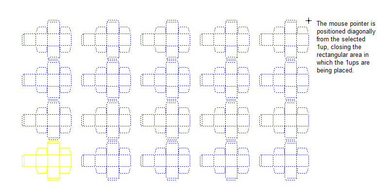
The selected 1up is multiplied automatically across the rectangular area, filling it full.