Video Tutorial: Creating layouts by using a predefined 2-parts-in-rows
template
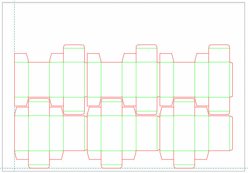
In this video we create a layout drawing
by using a predefined template. This automates the placement of the layout
1ups in the layout, as well as their relative situation.
Visual: Creating layout using a 2-parts-in-rows template
Click the icon to watch the video. Run time: 1:18 min.
PROCEDURAL STEPS
Having A2420 Straight Friction Tuck.evr open, insert EVF11040 Straight
Friction Tuck.evr: On the File menu, click Insert Drawings.
In the Insert Selected Drawings dialog box that appears,
select EV Resizable Design (*.evr) from the Files of type list,
point to EVF11040 Straight Friction Tuck.evr, click Add, and
then Insert.
To use the original name of the drawing to be inserted, in the
Enter new drawing name dialog box that appears, click OK.
To directly invoke the wizard, make sure the Run
layout wizard check box is selected.
Choose a template: from the Predefined Template combo box
of the Select Template step, select 2 parts in rows,
and then clickNext.
In the Select Template step, for the second row, select
the EVF11040 from the lower Drawing combo box, and then click
Next.
The Sheet Placement step appears.
In Correction, enter a value of 5 mm for vertical correction.
(This is the vertical gap between the rows in the layout.)
note: A gap of 3 mm or
more is considered necessary due to the fact that if the parts are adjoined,
the cutting rule will have to change direction too abruptly, which is
technologically hard to accomplish.
To select a sheet type, in the Sheet Placement step, from
the list next to Sheet Name, select the Bobst SP 102/3/4 sheet.
 .
.