Fixing a design by a wizard goes through five steps, each of which provides different type of fixing:
NOTE: Depending on the type of fixing that you want to do, you can use the following procedure from start to finish — to go over each type of fixing — or use individual fixing.
NOTE: Unless you select objects, the wizard will apply the transformations throughout the design.
The wizard appears at the Parallel Fix Tool page.
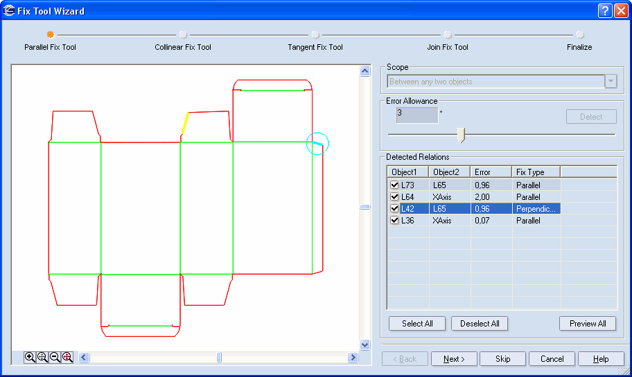
Scope Determines on what objects the detection will be performed.
Between any two objects Checks the entire design for parallel lines. A match that meets the error allowance appears in the Detected Relations table.
Between selected objects Checks for parallel lines only the selected objects. A match that meets the error allowance appears in the Detected Relations table.
Between selected and any other object Checks for parallel lines only the selected objects in reference to any other ones. A match that meets the error allowance appears in the Detected Relations table.
Error Allowance Sets the error allowance. This is the margin into which the dimensions of a line may fall without the line losing its parallelism with other objects. To set an allowance, you can use either the box or the slider. The bigger the error allowance, the greater the number of lines that would be in parallelism with the selected line.
Detect Begins checking the design when a new error allowance has been set.
Detect Relations A table listing the lines to which parallel transformation can be applied, as well as the reference lines.
Object1 Objects to which parallel transformation can be applied. Use the check boxes in front of the object IDs to select the objects that you want.
Object2 Objects to which the objects in the Object1 column can be parallel.
Error Displays the deviation (error) of the object in the Object1 column that needs to be corrected so that it is parallel to the object in the Object2 column. The Fix Tool Wizard will detect only the objects that fall within the set error allowance.
Fix type Determines the type of relation that the objects will obtain after applying the transformations. NOTE: Most often, the name coincides with that of the currently opened tab.
The Collinear Fix Tool page appears.
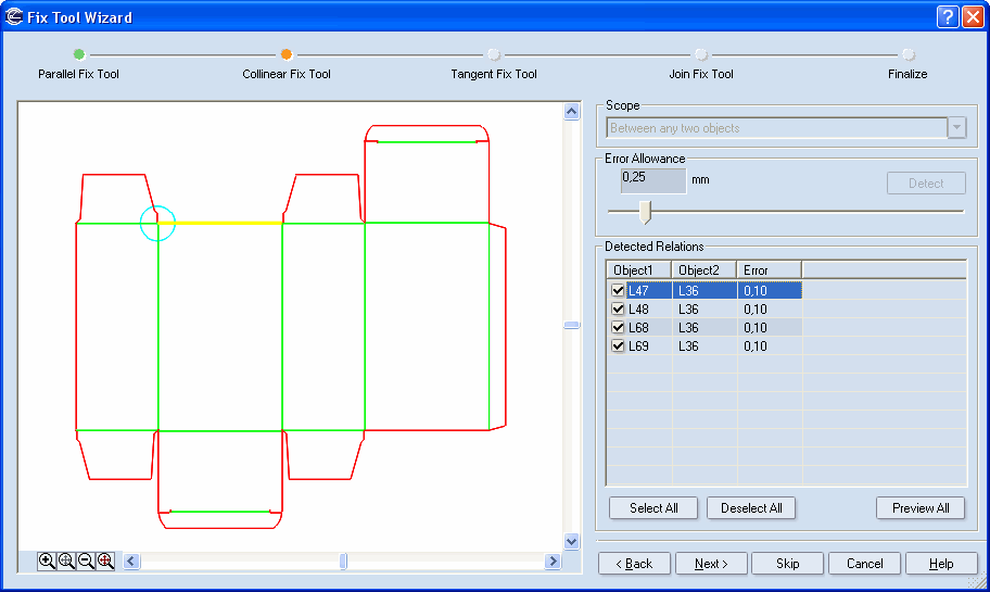
Scope Determines on what objects the detection will be performed.
Between any two objects Checks the entire design for parallel lines. A match that meets the error allowance appears in the Detected Relations table.
Between selected objects Checks for parallel lines only the selected objects. A match that meets the error allowance appears in the Detected Relations table.
Between selected and any other object Checks for parallel lines only the selected objects in reference to any other ones. A match that meets the error allowance appears in the Detected Relations table.
Error Allowance Sets the error allowance. This is the margin into which the dimensions of a line may fall without the line losing its parallelism with other objects. To set an allowance, you can use either the box or the slider. The bigger the error allowance, the greater the number of lines that would be in parallelism with the selected line.
Detect Begins checking the design when a new error allowance has been set.
Detect Relations A table listing the lines to which parallel transformation can be applied, as well as the reference lines.
Object1 Objects to which parallel transformation can be applied. Use the check boxes in front of the object IDs to select the objects that you want.
Object2 Objects to which the objects in the Object1 column can be parallel.
Error Displays the deviation (error) of the object in the Object1 column that needs to be corrected so that it is parallel to the object in the Object2 column. The Fix Tool Wizard will detect only the objects that fall within the set error allowance.
Fix type Determines the type of relation that the objects will obtain after applying the transformations. NOTE: Most often, the name coincides with that of the currently opened tab.
The Tangent Fix Tools page appears.
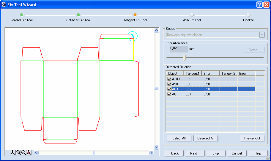
Scope Determines on what objects the detection will be performed.
Between any two objects Checks the entire design for curvilinear objects that can be transformed so that they get tangent lines. A match that meets the error allowance appears in the Detected Relations table.
Between selected objects Checks between the selected objects for curvilinear objects to be transformed into ones with tangent lines. A match that meets the error allowance appears in the Detected Relations table.
Between selected and any other object Checks for curvilinear objects the selected objects in reference to any other ones. A match that meets the error allowance appears in the Detected Relations table.
Error Allowance Sets the error allowance. This is the margin into which a curvilinear object may fall without its losing its tangency to other objects. To set an allowance, you can use either the box or the slider. The bigger the error allowance, the greater the number of curvilinear objects that will be tangent to a match.
Detect Begins checking when a new error allowance has been set.
Detect Relations A table listing the curvilinear objects to which tangent transformation can be applied, as well as the reference objects.
Tangent1 Displays the objects to which tangent transformations can be applied. Use the check boxes in front of each object IDs to select the objects to which you want tangent transformation applied.
Tangent2 Displays the objects that can be tangent to the ones in the Object 1 column.
Error Sets the deviation (error) of the object in the Tangent1 column that needs to be corrected so that the object in the Object 2 column becomes tangent to it. The Fix Tool Wizard will detect only the ones that fall within the error allowance. There are several Error columns, because the potential objects that can be tangent to an object in the Tangent1 column are more than one. Each Error column displays the deviation that needs to be corrected with regard to the objects in the Tangent2 column.
Fix type Determines the relation that the objects will obtain after the transformations are applied. NOTE: Most often, the name coincides with that of the currently opened tab.
The Join Fix Tools page appears.
NOTE: You can use the Join Fix Tool separately. To start it, on the Transformations menu, point to Fix Tools, and then click Fix Wizard.
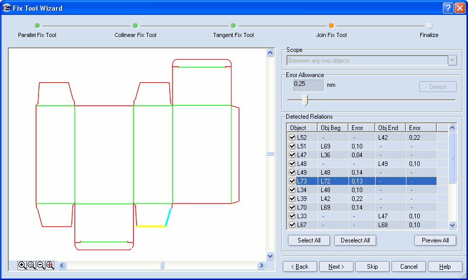
Scope Determines on what objects the detection will be performed.
Between Any Two Objects Checks the design for objects that can be joined. A match that meets the error allowance appears in the Detected Relations table.
Between Selected Objects Checks between the selected objects for objects to be joined. A match that meets the error allowance appears in the Detected Relations table.
Between Selected And Any Other Object Checks the selected objects in reference to any other ones to find objects to be joined. A match that meets the error allowance appears in the Detected Relations table.
Error Allowance Sets the error allowance. This is the permitted deviation (error) in the distance between two objects. The distance may be compensated by a segment and a joining relation is added so that the two objects become joined. You can use either the box or the slider to set the allowance. The bigger the allowance, the greater distance between objects will be detected.
Detect Begins checking when a new error allowance has been set.
Detect Relations A table listing the objects to which joining transformation can be applied.
Object Displays the objects to which joining transformations can be applied. Select the check boxes of the objects that you want transformed. Since transformations can be applied to both object ends, there are two Error columns for corrections of object beginning and object end, respectively.
Obj Beg Information about the objects to which the beginning point of the objects in the Object column can be joined.
Obj End Information about objects to which the end point of the objects in the Object column can be joined.
Error Sets the error between an object in the Object column and the objects to be joined at the ends. The error reveals into the distance between the selected in the Object1 column object's beginning/end points and objects that may be joined to these points. The error is eliminated by applying the joining transformation. There may be many objects with different error range, but the wizard will detect only those that fall within the error allowance.
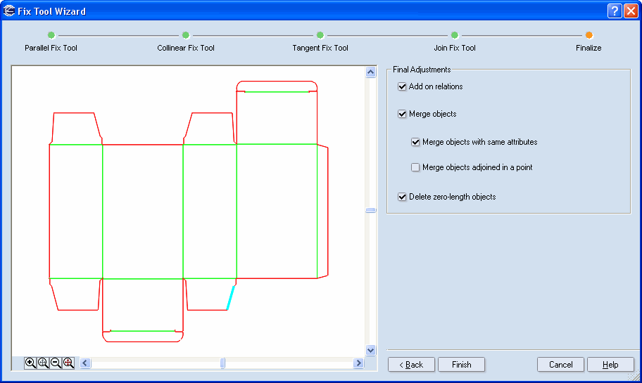
Final Adjustments
Add on-relations Adds on-relations at all possible places on the design.
Merge objects Merges objects across the design.
Merge objects with same attributes Merges the design's objects which have the same properties. For details, see Editing object properties.
Merge objects adjoined in a point Merges the design's objects adjoined in a point. For details, see Merging duplicated, adjoined objects.
Delete zero-length objects Deletes hard-to-discern objects that may have remained after the transformation. This option makes sure that all these objects are deleted.