.
.In rotating a geometric object, the program moves it from its original position to a new location by rotating it at an angle. Apart from rotating, the object can also be copied, which results in two objects: the original and the rotated one.
To rotate an object or a series of objects
.A contextual edit bar appears above the graphical area.
 Copy Leaves a copy of the original object.
 Select Distance (Available when a center of rotation is set) Starts the mode for selecting the object whose angle will serve as reference in the rotation. For an example of how to use this functionality, see Example 2 and Example 3 below.
Step angle Rotates the objects at angle intervals equal to or divisible by the value. Leave empty if you do not want to specify a step angle.
Rot. Angle Rotates the objects at the entered angle value.
NOTE: The Rotate button appears only if there is at least one selected object in the drawing.
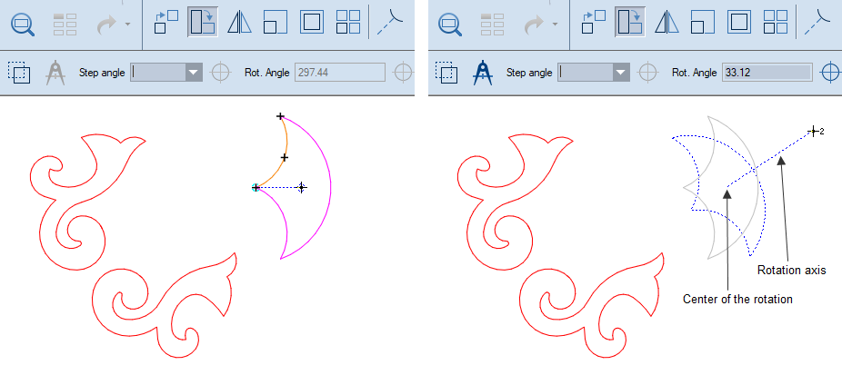
to keep the original objects in place.During rotation the program shows relations between the axis of rotation and the rest of the objects. When we need to rotate a selection so that one of its lines (reference line) points in a certain direction — for example, to become horizontal or vertical — it is best to use the technique described below. During the rotation, we will make the axis of rotation and the reference object collinear; thus the relations the program indicates will apply also to the reference object.
.A contextual edit bar appears above the graphical area.
.
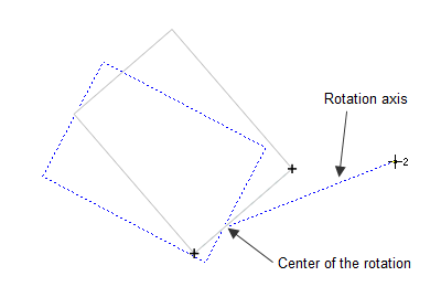
The center of rotation has been set.
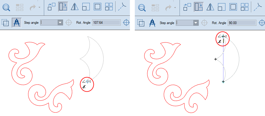
Now the axis of rotation is collinear to the reference line:
We begin moving the mouse until we find the rotation position that we need. The mouse pointer indicators indicate the detected relations to the coordinate axes: parallel to the y-axis (left) and parallel to the x-axis (right).
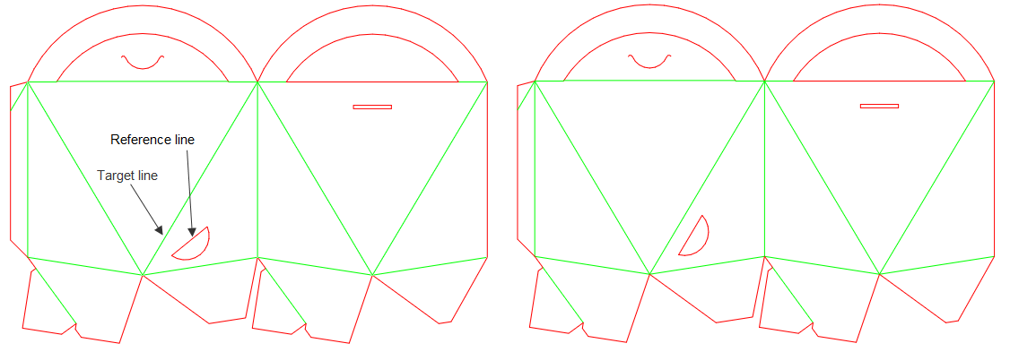
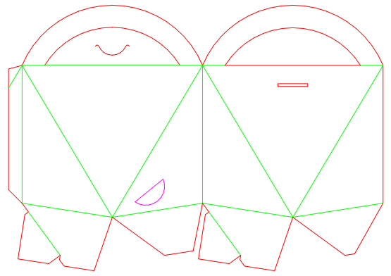
The following example teaches you how to rotate a selection so that one of its lines (called reference line) becomes parallel to a line outside the selection (called target line).
We will rotate the hole so that its straight section (the reference line) becomes parallel to the box's crease line (the target line). Consider the picture:
 .
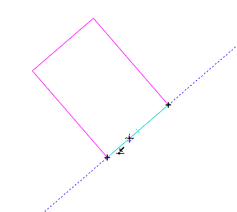
.Notice that the program automatically goes into the Detect Relations With Pointed-To Objects Only mode. In this mode, each pointed-to object — any object the mouse pointer goes through — is highlighted and its ends are marked by little cross marks (pictured).
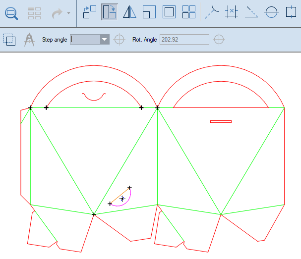
HINT: To clear the set of pointed-to objects, press CTRL. As a result, the pointed-to objects are no longer highlighted and the cross marks disappear.
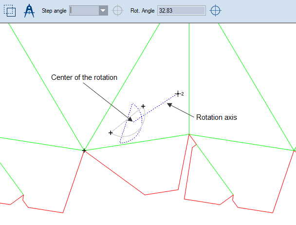
The center of rotation has been set.
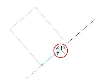
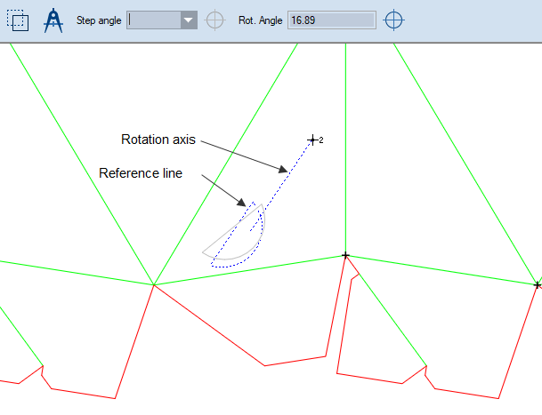
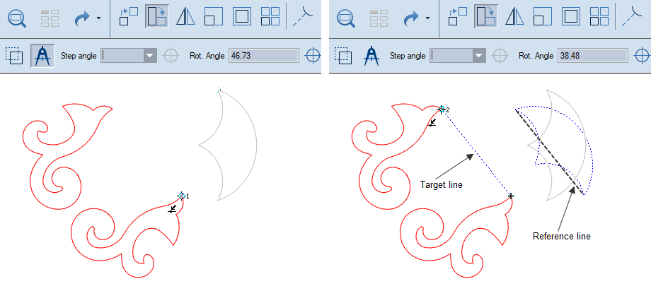
We proceed by setting the reference angle, which we will use to rotate the selected shape. We will extract this angle by pointing to an object from the selection.
 .
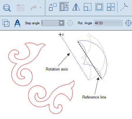
.IMPORTANT: Before clicking, wait until you see a little compass at the cursor (pictured). This type of cursor indicates that you are in the mode for extracting line angle.
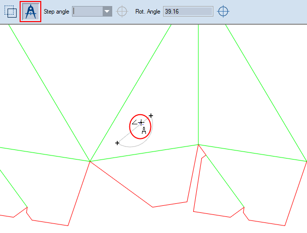
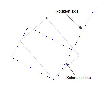
The reference line is set. Notice that the rotation axis is now parallel to the reference line:
We now move to setting a target line.
.IMPORTANT: Before clicking, wait until you see a little compass at the cursor (pictured). This type of cursor indicates that you are in the mode for extracting line angle.
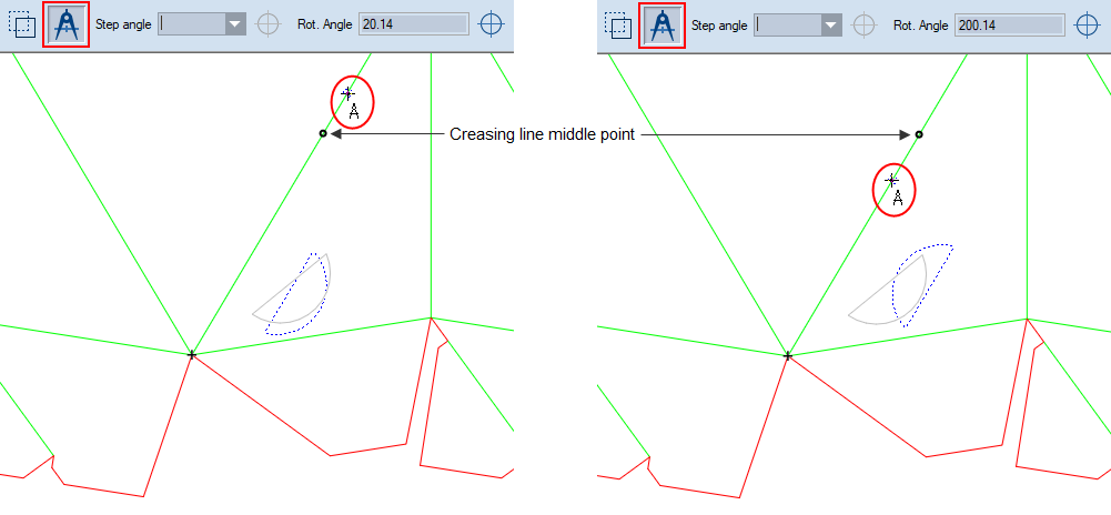
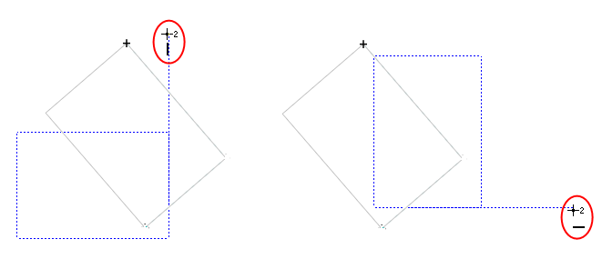
NOTE: There are two positions the selection can take on to accomplish the task. These are visualized depending on where you click with respect to the middle of the target object.
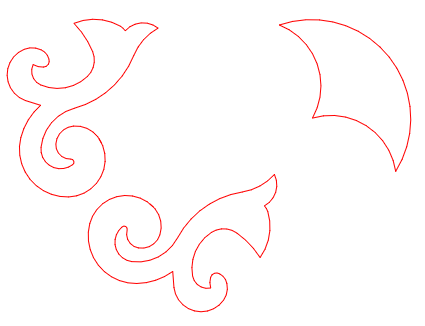
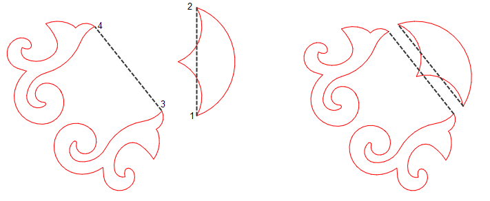
This technique consists in the rotation of a selection by defining virtual reference and target lines. In this case, we will use two clicks (1, 2) to define a virtual reference line in the selection. We then proceed to make this virtual line parallel to another virtual line defined by two other points (3,4).
 .
.
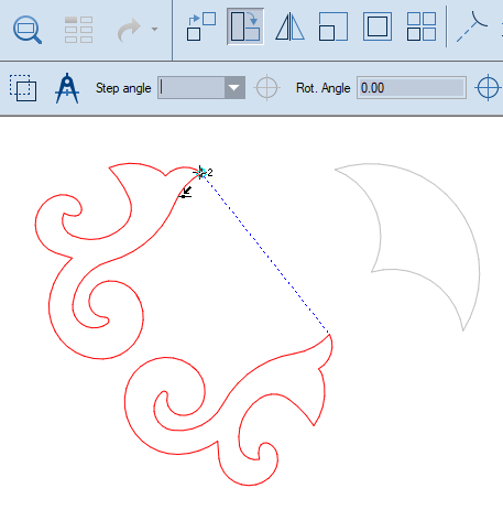
We proceed by setting the virtual reference line, which we will use to rotate the selected shape.
.IMPORTANT: Notice the graphics the cursor acquires while we click. For Point 1, the numeral 1 appears at the cursor, indicating that we are in the two-point angle-extraction mode. When next we click Point 2, a small numeral 2 appears at the cursor. This indicates that the definition of the reference line and the extraction of its angle have been completed.
The rotation axis has become parallel to the reference line defined by the two points we clicked in the selection:
Next we will set the virtual target line. We'll do this by two clicks.
, and then click consecutively Point 3 and Point 4.IMPORTANT: Notice the graphics the cursor acquires while we click. For Point 3, the numeral 1 appears at the cursor, indicating that we are in the two-point angle-extraction mode. When next we click the Point 4, a small numeral 2 appears at the cursor. This indicates that the definition of the target line and the extraction of its angle have been completed.
The program has extracted the target angle and rotated the selection so that the virtual reference line is now parallel to the virtual target line: