Copy Leaves in place the original object.
In scaling a geometric object or a series of objects, the program resizes them both horizontally and vertically in respect to a point and according to coefficients which you define.
 ==========================================
=
==========================================
===========================================
Scaling properties
Copy Leaves in place the original object.
 Select Distance (Available when a target object is selected in the modes translations, scaling, mirroring and rotating) Starts the mode for selecting the object whose distance will serve as reference in the transformation modes translation, scaling, mirroring and rotating. For an example of how to use this functionality, see Example 2 below.
Select Distance (Available when a center of scaling is set) Starts the mode for selecting the object whose length will serve as reference or target in the scaling. For examples of how to use this functionality, see Example 2 and Example 3 below.
 Proportional Scale Keeps the proportional (Ox-Oy) balance of the original objects into the scaled ones — that is, scales the objects evenly along the coordinate axes. When this mode is being used, the properties Scale Y and Step Y are unavailable.
Scale X Sets the coefficient by which the objects are scaled horizontally. (Must be greater than 0.00.) A value of 1.00 makes the scaled object of the same length projected along the x-axis as the original one. A value greater than 1.00 will make the object longer; a value between 0.00 and 1.00 will make the object shorter.
Y Sets the coefficient by which the objects are scaled vertically. (Must be greater than 0.00.) A value of 1.00 makes the scaled object is of the same length projected along the y-axis as the original one. A value greater than 1.00 will make the object taller; a value between 0.00 and 1.00 will make the object shorter. Unavailable in proportional scaling, when the scale coefficient in Scale X is applied for both coordinate directions.
Step X Sets a horizontal step coefficient. (Must be greater than 0.00.) The objects are scaled horizontally only by the Scale X coefficients that are equal to or divisible by the value in Step X.
Y Sets a vertical step coefficient. (Must be greater than 0.00.) The objects are scaled vertically only by the Y coefficients that are equal to or divisible by the value in Y. Unavailable in proportional scaling, when the scale coefficient in Scale X is applied for both coordinate directions.
Reference A length value that should be scaled so as to acquire the length of another object.
 .
.A contextual edit bar appears above the graphical area.
..NOTE: When the Proportional Scale button is pressed in, Scale Y and Step Y are unavailable, and EngView applies the scale coefficient (Scale X) and step value (Step X) to both coordinate axes.
A dynamic image of the scaled object, or objects, appears.
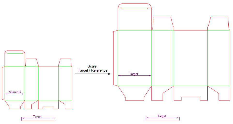
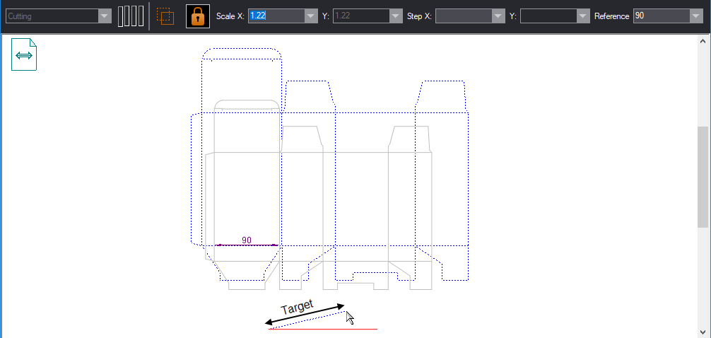
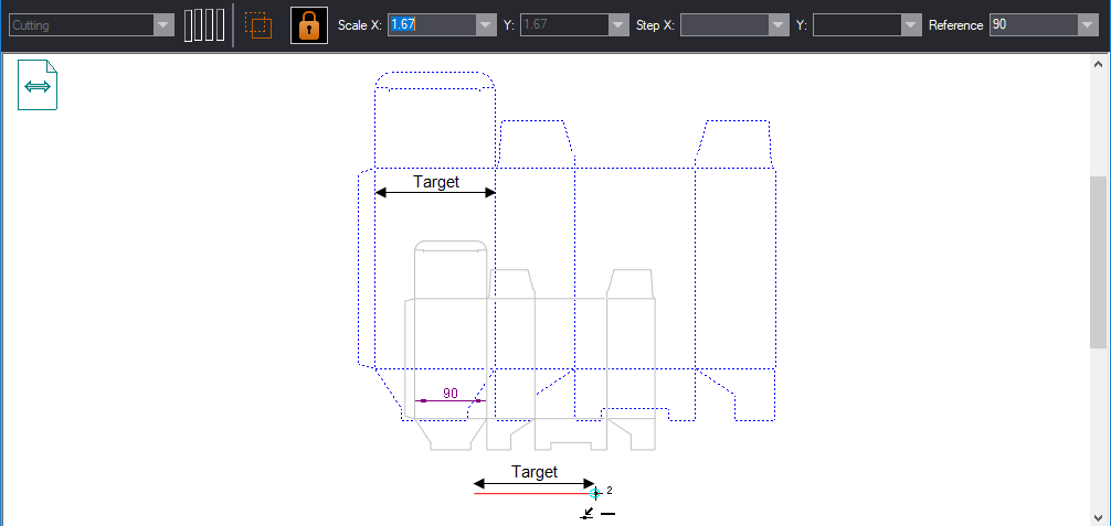
Scaling by a reference is most often applied when you want an object or distance — called reference — from a selection to adopt the length of another object or distance — called target. You do so by:
As a result, the program computes a scaling factor between the two values. The computed scaling factor — target/reference — is then applied to the entire selection.
You can set the reference:
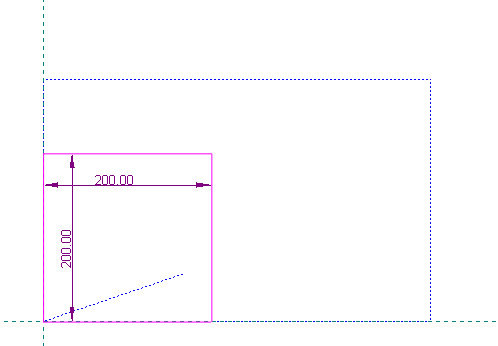
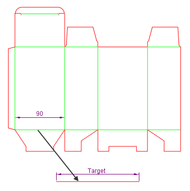
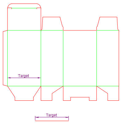
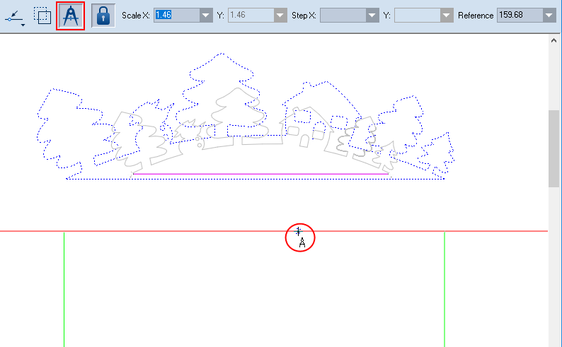
For example, you have a box sized 90 x 60 x 150, which you will scale proportionally so that the width 90 becomes identical with the length of an object outside the selection (pictured).
. is not pressed in.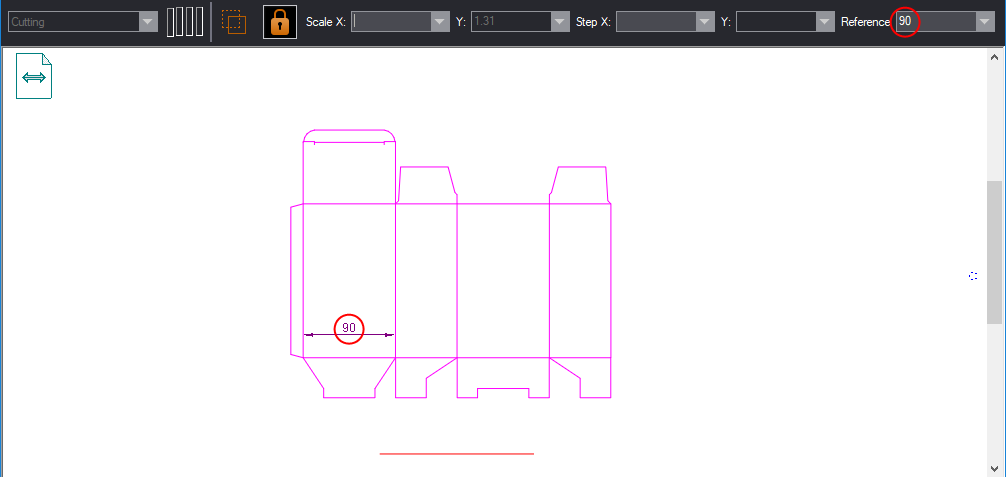

A new design has appeared, which is a scaled version of the original. Since no copying of the original object was chosen, the original design has disappeared.
============
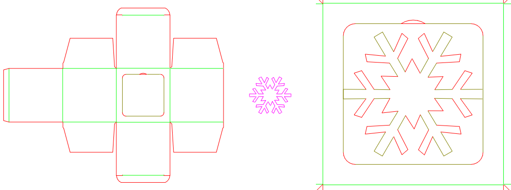
The technique consists in the scaling of a selection by extracting a reference from the length of one of its objects, and then making it equal to a target distance.
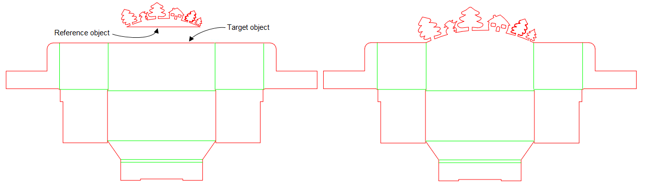
We will use the reference object from the forest shape and will make it equal to the structure's target object.
1. Select the shape.
2. Do any of the following:
.The program automatically goes into the Detect Relations With Pointed-To Objects Only. (A pointed-to object is any object the pointer goes through.) In this mode, each pointed-to object is highlighted and its ends are marked by little cross marks (pictured).
HINT: To clear the set of pointed-to objects, press CTRL. As a result, the pointed-to objects are no longer highlighted and the cross marks disappear.
3. To define the center of scaling, click anywhere.
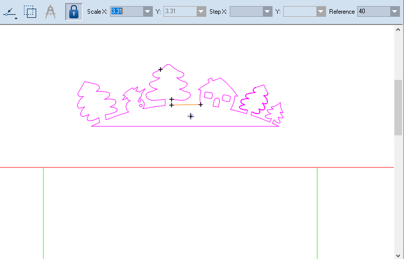
We proceed by setting the reference distance, which we will use to scale the selected shape. We will extract this distance by pointing to an object from the selection.
4. On the contextual edit bar, click Select Distance .
5. Press and hold down CTRL, and then point to the object that you want to use as reference, and then click.
IMPORTANT: Before clicking, wait until you see a little compass at the cursor (pictured). This type of cursor indicates that you are in the mode for extracting object length.
A reference object has been set, whose length has been recorded in Reference on the contextual edit bar.
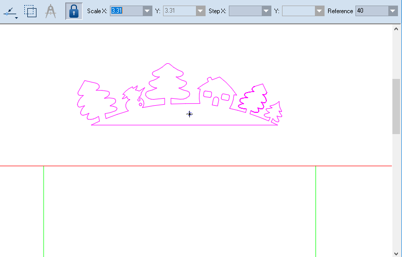
Then we move to setting a target distance by using an object's length.
.IMPORTANT: Before clicking, wait until you see a little compass at the cursor (pictured). This type of cursor indicates that you are in the mode for extracting object length.
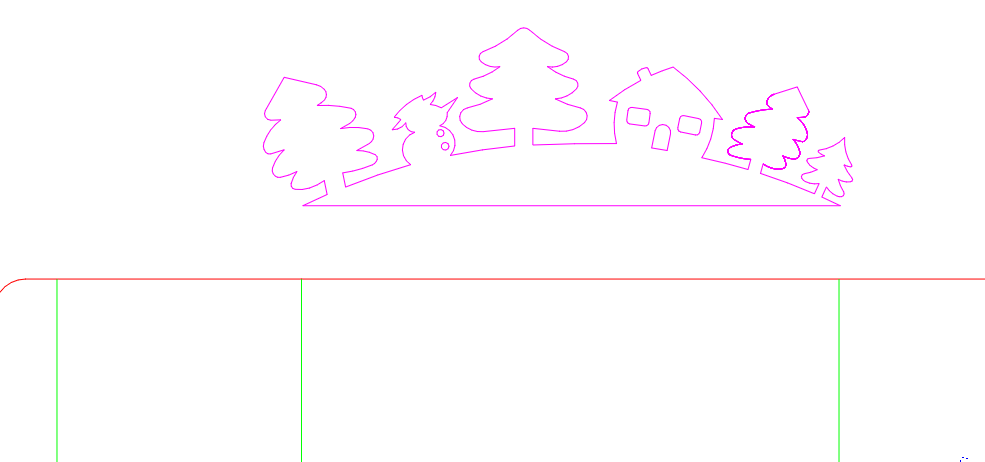
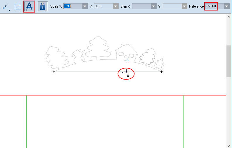
The selection has been scaled so that the reference object has acquired the distance of the target object.
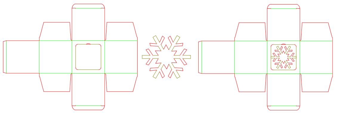
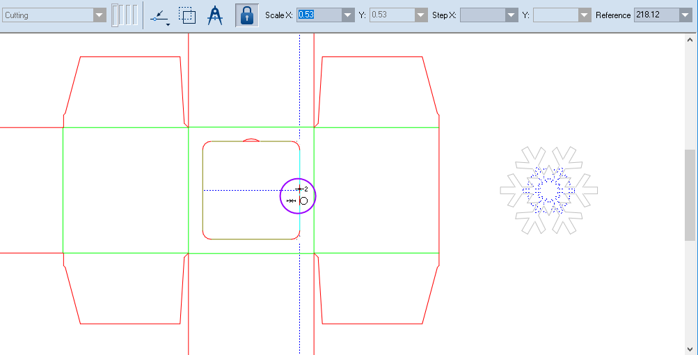
This technique scales a selection by extracting a reference by the distance between any two clicks and making it equal to a target distance. There are cases in which no suitable object exists to use as a reference for the drawing you want to scale. In such situations, you can use as a reference the distance between two control points (including a middle point). Follow the technique that follows, in which a snowflake fits a perforated hole (pictured).
.At this point the program begins to automatically detect the relations available to the objects you touch with the mouse pointer. Relations with other objects are ignored.
HINT: To clear the set of pointed-to objects, press CTRL. As a result, the pointed-to objects are no longer highlighted and the cross marks disappear.
To define the center of scaling, click anywhere.
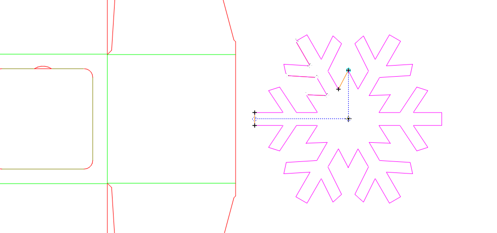
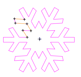
Note that, to precisely target the center of the snowflake, we have used two pointed-to (highlighted) objects.
We proceed by setting the reference distance, which we will use to scale the selected shape. We will extract this distance directly from the drawing.
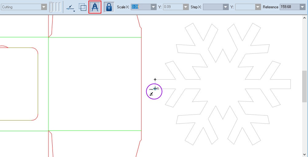
.The cursor becomes the Reference Point 1  . This indicates that you are about to extract a reference distance.
IMPORTANT: Before clicking the first control point, make sure you see the numeral 1 at the cursor (pictured). This indicates that you are in the two-point reference distance extraction mode.
After you click the first control point, the cursor becomes the Reference Point 2  . This means that you are about to click the second reference point.
IMPORTANT: Before clicking the second control point, make sure you see the numeral 2 at the cursor (pictured).
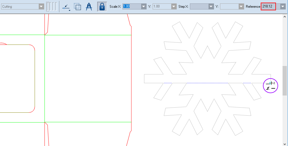
You have now set the reference distance, which appears in Reference.
Next we will set the target we're after. We'll do this by extracting the distance with two clicks.
.The cursor becomes Set Target 1  . This indicates that you are about to extract the target distance.
IMPORTANT: Before clicking the first control point, make sure you see the numeral 1 (pictured). This indicates that you are in the two-point target distance extraction mode.
After you click the first control point, the cursor becomes Set Target 2 . This means that you are about to click the second control point.
IMPORTANT: Before clicking the second control point, make sure you see the numeral 2 at the cursor (pictured).
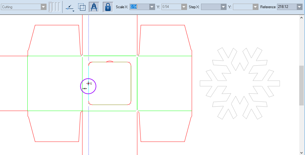
The program has extracted the target distance and applied a scaling factor to the selected shape — calculated according to the target/reference formula.