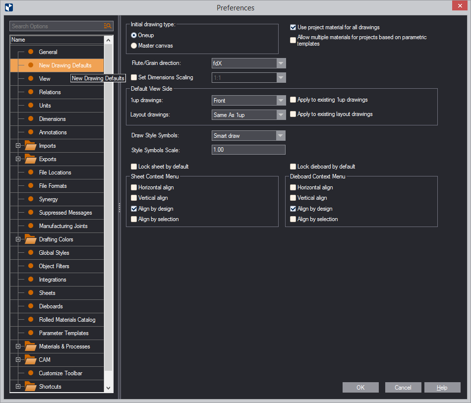
In this pane, you set up the defaults for new drawings. Specifically, you set up:

| New Project Defaults | Settings for (1) the type of startup drawing and (2) how many types of materials will be used across a project. |
|---|---|
| Initial drawing type | The type of drawing that a new project will start with: an empty 1up or a Master Canvas drawing. |
| Use project material for all drawings | Select the check box to use the material you have selected for the project in all the drawings you plan for the project. Leave the check box empty if you want to use separate materials for each drawing. |
| Flute/Grain direction | The default direction
of the flute (grain) for new drawings.
NOTE: For jobs that start from a parametric template (an .evr file) or an external 3D object, the direction of the flute (grain) is predefined. For nonresizable and imported drawings, you need to set the direction of the flute (grain). |
| Set Dimensions Scaling | (empty by default)
In this group, you set the pattern for how dimensions texts,
as seen on the screen, are scaled when the drawing is exported
or printed out.
NOTE: The scaling pattern set here affects only the drawings that will be created after you click OK in this dialog box. Drawings created earlier will not be affected. Still, regardless of what you set here, you can set custom scaling patterns for each individual drawing. |
| Default View Side | In this group, you tell
EngView
which side to display in the graphical area for new 1up and
layout drawings. The options: Same as 1up (layout drawings
only), Front, Rear, Diecutting, Counterdiecutting.
NOTE: The diecutting side is a property of the material and has been specifically defined for it. Before setting a diecutting or counterdiecutting side as a default side, check which the diecutting side is for your material, and then decide how you want to set the default. |
| 1up drawings | The side that will be visible for a new 1up drawing. The options: Front, Rear, Diecutting, Counter-Diecutting. |
| Layout drawings | The side that will be visible for new layout drawings. The options: Same as 1up, Front, Rear, Diecutting, Counter-Diecutting. |
| Apply to existing 1up, layout drawings | When you select the Apply to Existing check boxes, what you have set for 1ups and layout drawings will apply also to files created before fixing the setting here. |
| Draw Style Symbols | Sets how style symbols
will appear on the screen in newly created drawings. The options
are:
|
| Style Symbols Scale | The scale factor that EngView will apply to reproduce the style symbols on the screen. Example: If a style symbol is 16x16 pixels, the scale factor 2 will increase its on-screen representation two times. |
| Lock sheet by default | In layout projects, the sheet is locked automatically. |
| Lock dieboard by default | In diemaking projects, the dieboard is locked automatically. |
| Sheet Context Menu | If selected here, the following commands will appear as context-menu commands when you right-click the sheet's outer edge. |
| Horizontal align | The sheet is aligned horizontally against the elements in the drawing. |
| Vertical align | The sheet is aligned vertically against the elements in the drawing. |
| Align by design | The sheet is aligned both vertically and horizontally against the layout 1ups in the drawing. |
| Align by selection | (Available when one or more layout 1ups are selected) The sheet is aligned by the selected layout 1up(s). |
| Dieboard Context Menu | If selected here, the following commands will appear as context-menu commands when you right-click the dieboard's outer edge. |
| Horizontal align | The sheet is aligned horizontally against the elements in the drawing. |
| Vertical align | The sheet is aligned vertically against the elements in the drawing. |
| Align by design | The dieboard is aligned both vertically and horizontally against the elements in the drawing. |
| Align by selection | (Available when one or more elements in the dieboard is selected) The dieboard is aligned by the selected element(s). |