 .
.You can generate optimized, associative tool paths, providing tool path trace animation of the cutting process and a fully configurable NC postprocessor for most NC controllers.
To create a tool path
NOTE: When you create a tool path (CAM) drawing of sample counters (counterplate drawing), the resultant CAM drawing will include only the sample counter objects — that is, the objects in Counterplates style.
 .
.
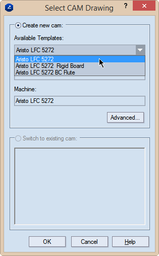
Create New CAM Use this option to create a new CAM drawing.
Available Templates In the dropdown, select the template that you want to work with in the new CAM drawing.
Machine (read-only) Displays the name of the machine to which the selected template is associated.
Advanced Opens a dialog box in which you can edit the selected template.
Switch to Existing CAM Use this option to switch to an existing CAM drawing created from the active source drawing (1up, layout or counterplate). This lets you choose not to create multiple identical CAM drawings from the same source drawing. NOTE: The list displays the names of existing CAM drawings created from the active 1up, layout or counterplate drawing.
NOTE: To show the tabular area if it is hidden, on the View menu, check Show tables.
 .
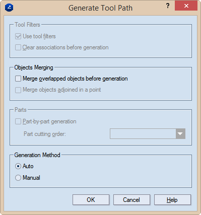
.The Tool Path Generation Options dialog box appears, in which you can set various options for tool path optimization. The optimal tool path is found automatically.

NOTE: The tool path relates to the respective drawing. If you modify the drawing, Prinect updates the tool path.
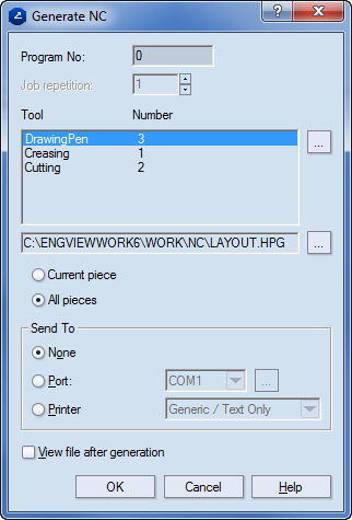
The NC Generation Properties dialog box appears, in which you can set NC generation options.

A file is generated with the NC code for your project (with the file name extension you have defined in the CAM template).