 .
.When a tool is processing a contour, portions of the material are lost due to the pressure the tool applies to the material. To prevent losing material mass, you can define a material side, a process in which you specify which side of the item being processed will be treated as foremost. This results in positioning the tool in a way that protects the integrity of the material and pressure is applied to the nonessential part of the sheet.
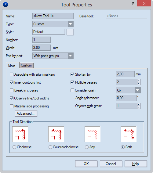
To define material side
The Tool Properties dialog box appears.
The Advanced Tool Properties dialog box appears.
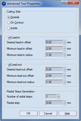
Cutting Side Specifies the zone where the cutting tool will go.
Outside The cutting is done on the outside of the contour, eating into the waste.
On contour The cutting is done along the contour.
Inside The cutting is done on the inside of the contour, eating into the material.
Lead-in
Minimum lead-in offset Sets the lowest applicable lead-in offset.
Desired lead-in offset Sets the lead-in offset that you want to have.
Minimum lead-in radius Sets the lowest applicable lead-in radius.
Lead-out
Minimum lead-out offset Sets the lowest applicable lead-out offset.
Desired lead-out offset Sets the lead-out offset that you want to have.
Minimum lead-out radius Sets the lowest applicable lead-out radius.
Radial Step Generation (Unavailable when "On contour" is selected in the Cutting Side area) Settings about how the tool should move when the when the material must be processed in a way that guarantees that the cutting line contour indicates the actual outer edge of the material after the processing has finished.
Number of radial steps Sets how many times the tool will pass along the contour to effect the processing of the material. Depending on the option selected in the Cutting Side area, this can be either outside the contour or inside it.
Radial step Sets the distance at which each next passage of the tool will differ from the preceding one. NOTE: Applies for the steps after the first one — that is, if there will be only one radial step, the value in Radial step will necessarily be zero (0).
.
Material and waste sides defined for areas around a cutting tool. The hatch indicates the material side.
A contextual edit bar appears above the graphical area.
 .
.NOTE: When you have started material side definition, the default material side is applied. You can either: (1) change it automatically, or (2) keep it and then use manual material side definition by applying the By Objects functionality.
The Select Material Side dialog box appears.
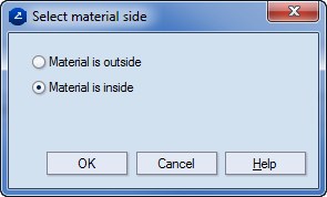
NOTE: Inside and outside refer to the sides around a contour: the area that a contour encloses is referred to as inside, the area beyond the contour, as outside.
 ,
and then in the graphical area use the mouse to set material side
along the contour, on the places where you want.
,
and then in the graphical area use the mouse to set material side
along the contour, on the places where you want.