 .
.To minimize cutting time, EngView provides high optimization of the tool path generation. If you have specific requirements, you can create additional tool filters for objects according to their styles, in order to associate them with the appropriate tools before tool path is generated. Associations with tools can also be manual. Also, you can set the direction of the tool manually — in some situations this is useful for the cutting tool.
Once you've generated the tool path, you can make the program take into account all these particular settings and optimize the tool path according to them. However, when you generate the tool path, any further corrections will remove the existing tool path it will have to be generated anew with regard to the new CAM environment. You can generate the tool path in a single CAM drawing multiple times. TIP: It is a better approach to edit the CAM environment before generating the tool path.
IMPORTANT: EngView initially generates separate optimized tool paths for each primary CAM tools according to the hierarchical order of the tools in the CAMTools tab: first the tool path of the topmost tool is generated, then that of the one below it, and so on. The separate tool paths are then automatically linked together in the same order. Nonetheless, you can generate a combined, optimized tool path for two or more tools by creating these tools as child tools of a primary (parent) tool and then creating tool filters that associate the relevant objects directly with the child tools. (This is useful for tools which can be changed quickly on the machine).
To create tool path
.NOTE: You cannot generate a tool path unless your currently loaded CAM template contains tool filters and you have manually created associations. In this case, you must either first create the necessary tool filters, or associate at least one object with an existing tool.
The Tool Path Generation Options dialog box appears. Consider the two situations:
When no associations are set for any object
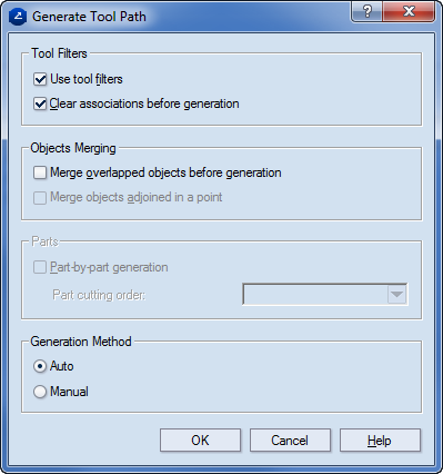
Tool Filters (Unavailable when you generate tool path without any set associations)
Use tool filters Turns on the tool filters during the generation of tool path. By using it, in a CAM template you can override the tool filters for a particular CAM drawing.
Clear associations before generation Removes all associations between objects and CAM tools.
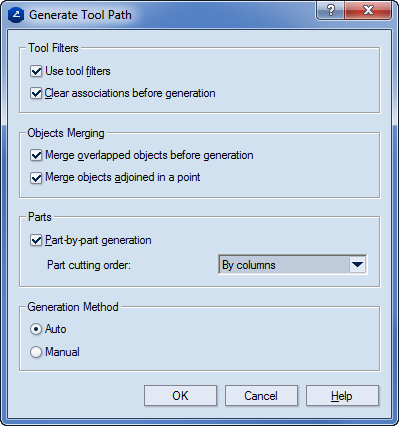
Objects Merging Merges duplicated or adjoined objects. Duplicated objects are either two collinear lines (not axes) or two arcs with the same radii and orientation, with a common, fully overlapping section. Adjoined objects are either two collinear lines (not axes) or two arcs with the same radii and orientation, with at least one common point that adjoins them.
Merge overlapped objects before generation Merges all duplicated (overlapping) objects with the same styles and object properties. For an example, see the bottom of this page.
Merge objects adjoined in a point Merges both duplicated and adjoined objects with the same styles and object properties. Unavailable when the Merge overlapped objects before generation is not selected. For an example, see the bottom of this page.
Parts (Available when you generate the tool path of a layout drawing)
Part-by-part generation Optimizes the tool path separately for each successive layout part. If the layout was made by manual insertion of parts, the CAM processing order will follow the order of insertion of the parts in the layout. If the check box is not selected, an optimized tool path for the whole layout will be generated — that is, the layout will be treated as a single structure.
Part cutting order Provides the following options:
Nearest part Optimizes the tool path, choosing the nearest part as next object for generation and, later on, for cutting.
By columns Optimizes the tool path, processing the parts by columns.
By rows Optimizes the tool path, processing parts by rows.
Generation Method Lets you choose between manual or automatic tool path generation.
When there is at least one association

TIP: Follow two examples for merging combinations.
Example 1. Merging of duplicated objects with identical styles and object properties.
Objects that will NOT be merged are:
Example 2. Simultaneous merging of duplicated and adjoined objects with identical styles and object properties.
Objects that will NOT be merged are:
A contextual edit bar appears above the graphical area.

 Previous entity
Scraps the generation of tool path along the last object.
Previous entity
Scraps the generation of tool path along the last object.
List Lists the objects along which you can generate a tool path.
 Next entity Takes
tool path generation to the next entity of the same type.
Next entity Takes
tool path generation to the next entity of the same type.
Previous object Takes
the tool path generation a step back.
Next step Displays the action that will be done to the path.
Next object Carries
out the next step down the object.
 Animate generation
Completes the generation of tool path along the design. The action is
visualized in the graphical area.
Animate generation
Completes the generation of tool path along the design. The action is
visualized in the graphical area.
 ToolUp with lead-out Takes the tool out of
the tool path by leading it out.
ToolUp with lead-out Takes the tool out of
the tool path by leading it out.
 ToolUp at position Takes the tool out of the tool path abruptly.
 ToolDown with lead-in Takes the tool
onto the tool path by leading it in.
ToolDown with lead-in Takes the tool
onto the tool path by leading it in.
 . The items
that you can choose from are: design, zone, part, tool and chain.
. The items
that you can choose from are: design, zone, part, tool and chain. .
.NOTE ON METHOD SELECTION: The difference between the two
methods has to do with the specifics of the tool path. The former choice
automatically creates a uniform tool path along the selected item. You
can continue with the next item by clicking Optimize entity again until the entire tool path
is created, or you can then switch over to an object-by-object tool path.
To return a step back, click Previous entity .
The latter method offers manual tool path generation
— it creates the tool path along each object giving you control over how
the tool path will apply over each next object. By using this method,
you can choose the type of tool movement: removing the tool with a lead-out
— ToolUp with
lead-out — removing
the tool abruptly — ToolUp at position — or
positioning the tool by leading it in — ToolDown with lead-in .