.
.You can define the direction of the tool explicitly for any object. Sometimes this is useful for the cutting tool — for example, when, depending on the default tool path directions, the tool would make a sharp turn at a very acute angle. Watch a brief video that explains the procedure.
IMPORTANT: If you have generated the tool path before you set the tool directions manually, you must generate the tool path again at the end.
To set tool direction manually
.
| Icon | Tool Direction | What It Does |
|---|---|---|
 |
From toolpath | Keeps some of the directions when you have created the tool path before you made manual direction changes. |
 |
Reverse direction | Reverses the current cutting direction for the object on which you will click. |
| Clear direction | Deletes the cutting direction for the object on which you will click. | |

|
Positive direction | Depending on which half of the object you click, sets the cutting in the same direction. EXAMPLE: If you click the right half of an object, the cutting direction will be to the right; if you click the left half, the cutting direction will be to the left. |
 |
Split from/to center | Splits the tool path in the object's middle. The cutting direction is
split differently depending on where you click:
|
To set tool direction by automatic detection
 .
.The Detect Directions dialog box appears.
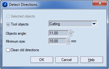
| Selected objects | (Available when objects are selected.) Applies the settings only to the selected objects. |
|---|---|
| Tool objects | (Available when no objects are selected.) In the dropdown list, select a style. EngView will apply the settings only to objects in that style. |
| Objects angle | Sets the highest angle at which two objects can meet for the settings to be applied. If the actual angle value is below the value set here, a tool path is generated for the objects. The cutting directions will move toward the point in which the objects meet. |
| Minimum size | Sets the shortest length that an object must have to be affected by the rule set in Objects angle to be applied. |
| Clean old directions | Clears any tool path directions set for objects and applies the newly set ones. |