Inserting components
You can assemble package designs out of ready components. By default, the library of ready-to-use components is located in the C:\EngViewWork7\Standards Library\mm\Synergy Components folder. You can access the components from the tabular area, in the Synergy Components tab. By default, the Library of Resizable Designs is located in the sub-folder C:\EngViewWork7\Standards Library\mm\Standards. (You can change the default locations of Synergy Components and resizable designs from File Locations tab, accessible by clicking Options on the Tools menu.)
After a component has been dragged into the graphical area, its relations and parameters are kept.
To insert a Synergy component
- In the table, click the Synergy Components tab, and then browse to the component you want to insert.
NOTE: To show the table if it is hidden, on the View menu, click Show tables.
- Select the component, drag it into the graphical area, and then click consecutively the control points to which you want to position it.
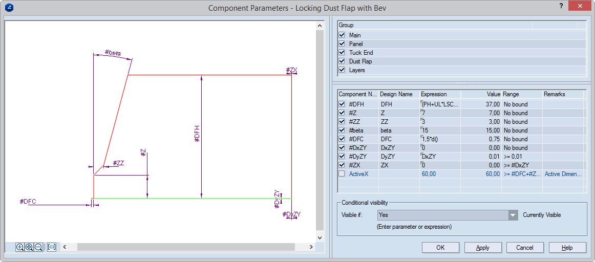
The Component Parameters dialog box appears.
NOTE: The Component Parameters dialog box appears each time you insert a new component. To edit parameters in an already inserted component, select the component, and then, in the contextual edit bar, click Component Parameters  .
.
Group List the parameter groups in the component. Each parameter in the table below is assigned to one or several parameter groups. To use an entire group of parameters results, leave its check box selected. By default, all available groups are selected. You cannot clear the Main group. For help on how to manage parameter groups, see Using parameter groups.
The table — For guidance as to how parameters affect the structure of the component, clicking a parameter row animates, in the preview area, the object that the parameter controls.
Component Name Displays the name of the component parameter as it was originally created. The # sign means that the parameter is set only for the component. When upon insertion the parameter row is highlighted in yellow, this means that it is not present in the project's list of parameters. Clear the check box to add it.
Design Name (filled when the check box in front of the name in Component Name is selected) The name with which the parameter will be entered in the project.
Expression Displays the expression the program uses for calculating value of the parameter. You can use mathematical expressions, functions and parameters positioned above the current one in the table.
Value Displays the value of the parameter as calculated according to the expression. If other parameters take part in the expression, the value is recalculated each time their values change.
Range The minimum and maximum value that the parameter can have.
Remarks Optional information about the parameter.
Conditional visibility Sets a condition about when the component will be visible. Learn more about this functionality.
- (Optional) In the Group area, choose which groups of parameters to include in the drawing. A selected check box includes a group; an empty one excludes it.
- (Optional) In the table, in Expression, modify the expressions of parameters.
About local parameters in a drawing
The #-marked parameters are local for the component and do not apply for the drawing in which the component has been inserted. Local parameters can be edited only in the parameter table of the component they belong to: in a drawing, select the component, and then double-click any of its objects or click Component Parameters on the contextual edit bar. In the table of the Components Parameters dialog box that appears, edit the local parameters.
To manage local parameters in a drawing
In a drawing, you can manage the local parameters by creating new parameters which you then associate with the local ones. The newly created parameters become part of the drawing's parameter table, from where you can edit them. When the parameters are modified in the table, the local parameters of the inserted component are modified accordingly.
To create new parameters
To create new parameters directly in the Component Parameters dialog box, in Expression, enter the name of the new parameter. In the Create Parameter dialog box that appears, in Expression, enter a value, another parameter, a mathematical expression or a function. The new parameter is added into the parameter table of the drawing, and can be managed there.
- In Conditional visibility, set a rule for when the component will be visible in the graphical area. Learn more about this functionality.
- Click OK to insert the component.
- (Optional) To insert more components, repeat Steps 1–6.
- To cancel the insertion of components, press ESC.
NOTE: In the expressions of component parameters, you can use mathematical functions.