| For |
FORMULA |
| Length |
$Fold3DN.BoundingBoxLength(, Units)$ |
| Width |
$Fold3DN.BoundingBoxWidth(, Units)$ |
| Height |
$Fold3DN.BoundingBoxHeight(, Units)$ |
NOTE:Units makes the formula extract
the dimension values in the currently used measurement
units. In formulas, the letters indicating the metrics (units)
must be in small case.
Examples
| To print |
Use |
Example |
| The length, in mm., of an inserted objects linked to
Fold3D1. Precision 2. |
$Fold3D1.BoundingBoxLength(, mm)$ mm. |
34.50 mm. |
| The width, in cm., of the inserted object linked to
Fold3D1. Precision 2. |
$Fold3D1.BoundingBoxWidth(, cm)$ cm. |
4.20 cm. |
| The height, in mm., of the inserted object linked to
Fold3D3. Precision 2. |
$Fold3D3.BoundingBoxHeight(, mm)$ mm. |
14.60 mm. |
NOTE: When citing the names of external objects,
pay attention to how they are placed into the respective predefined
areas.
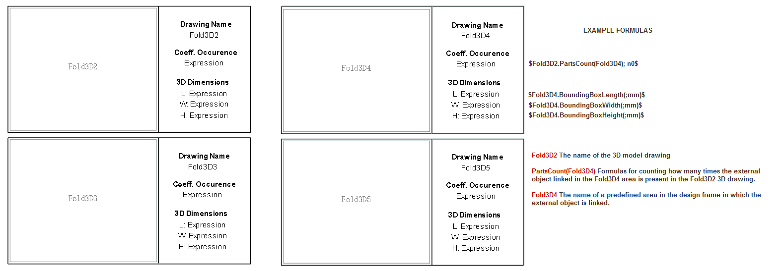
IN THE DESIGN FRAME
In the following table, the left frames cite the predefined
areas. All dimensions-extracting formulas in the right frames
refer to the objects placed into the predefined areas.
IMPORTANT: In design frames, Expression
means that a formula is correctly entered and will produce an
actual result when the design frame is applied in a print drawing.
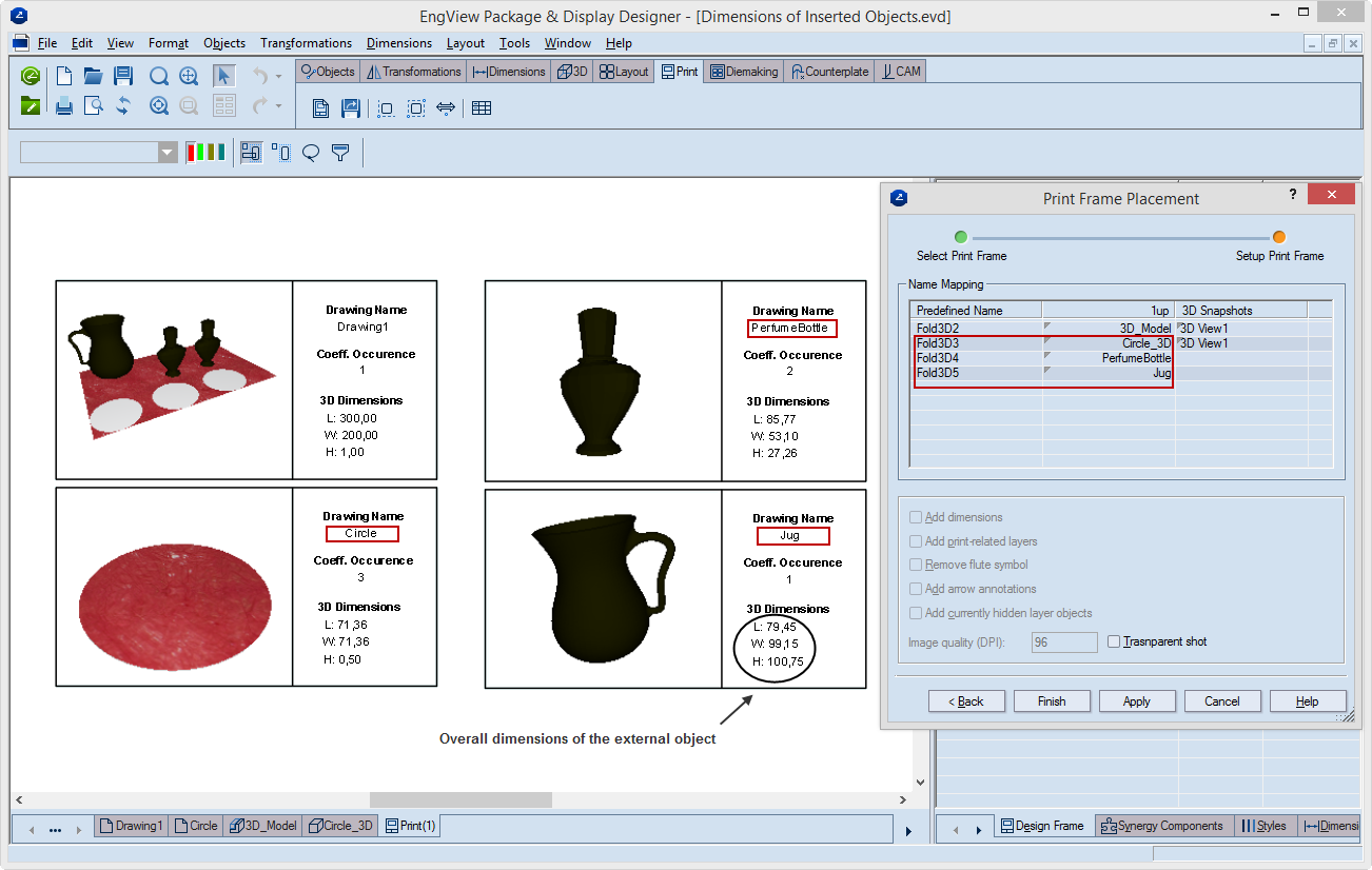
IN THE PRINT DRAWING
The following pictures shows how external objects are linked
to predefined areas as pictured above. While you are setting up
the print drawing, you refer the external objects to the predefined
area names. In the Print Frame Placement dialog box, you
refer the external objects to the predefined areas. When in the
dialog box you click Apply, you will see how the formulas
are applied and the external objects displayed in the predefined
areas.
IMPORTANT: Note the actual extracted overall
dimensions of external objects under 3D dimensions.