 .
.While creating an array manually, you can use the automatic detection of parts' edges. While you are placing a part into the graphical area (into a sheet), the program detects the outer edges of the parts that are already in the sheet and marks the no-go areas — that is, the areas you cannot use for placing new parts. The functionality prevents the parts that are about to be placed from overlapping the existing parts in the array. The edge detection ensures that:
Depending on your technological case, you can use edge detection also when bleed is applied on the layout 1ups (parts).
.The contextual edit bar expands, displaying the edge detections controls:

The edge detection controls (highlighted in red) are as follows:
 Use Sheet Border as Placement Barrier Click this button if you want the program to restrict the movement of layout 1ups when they reach the sheet's outer border. A visual indication lets you know that you have reached the sheet's border. The functionality makes it easier to place layout 1ups (parts) into the sheet by sparing you the need to pay close attention while placing a part near the edge area.
 Use Placement Snap Point Normally, layout 1up (parts) have multiple control points. You can select any one of them that is most convenient and use it for dragging the layout 1up into the sheet and positioning it. See how to set the snap point in a part. TIP: While you are dragging a part, you can again switch the snap point at any moment by holding down CTRL and then moving the mouse around the part and selecting a different snap point.
Gap Enter a value for a gap that you want to separate the layout 1ups (parts) in the array. If you use gap, the automatic edge detection will work by taking account of the gap.
The following picture describes how edge detection works. The green design is being placed along the red one. NOTE: The design placement is done along the designs' cut lines; the bleeds are not taken into account.
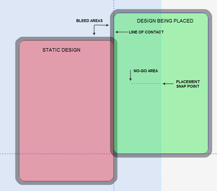
In the example, the green design is being dragged through its central snap point. After the design's leftmost cut line reaches the red design's rightmost cut line, the green design's movement stops and a line of contact is formed — the line where the two design's cut lines meet. If you continue moving the mouse leftward, the green design does not move; the dashed line at the mouse pointer indicates that the green design's left border has reached the right edge of the red design and cannot go farther.