Fixing drafting errors in imported files
Files created outside of and imported into EngView often contain drafting errors that prevent projects from further processing. These errors may lead to constructional imperfections — for example, unclosed contours, creases and cuts that lead nowhere, and objects that fall outside the requirements for geometric relations — nearly overlapping, nearly parallel or nearly collinear line sections, or nearly coincidental arcs.
The Fix Assistant tool inspects geometric elements, detecting errors according to criteria that you set — angle and distance allowances, minimum areas and object size, crease line limits. After a file is imported and criteria are set, Fix Assistant uses them to produce a list of drafting errors. Then you decide which errors are critical and need to be fixed and which can stay as they are.
- In the drawing that contains the imported file, do any of the following:
- On the Transformations toolbar, click Fix
Assistant
 .
. - On the Transformations menu, click Fix Assistant.
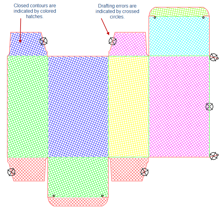
In the graphical area the closed contours are indicated by colored hatches. The drafting errors that fall within the values set by default are indicated by crossed circles.
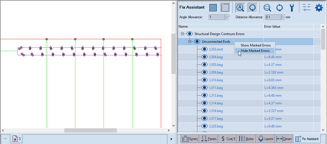
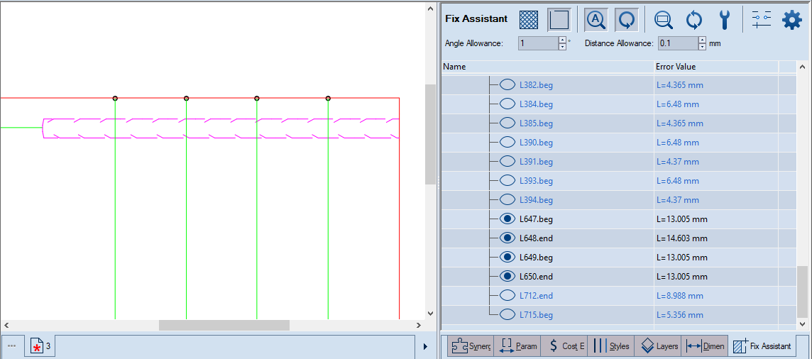
Errors in 1up drawings
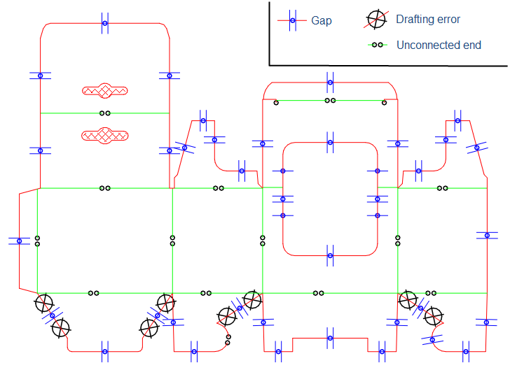
Errors in imported bridges drawings
In the tabular area, the Fix Assistant tab appears, in which the detected errors are listed in groups by technical features.
The controls
 Hatch Contour
Indicates the closed contours with colored hatches.
Hatch Contour
Indicates the closed contours with colored hatches.
 Ignore Near-Zero-Length Unconnected
Ends The program does not detect gaps of near-zero lengths. The
functionality applies primarily to tangential objects and unconnected
ends.
Ignore Near-Zero-Length Unconnected
Ends The program does not detect gaps of near-zero lengths. The
functionality applies primarily to tangential objects and unconnected
ends.
 Toggle Auto Zoom
When the button is pressed in, each time an issue is selected in the
table, the zoom automatically moves to it in the graphical area.
Toggle Auto Zoom
When the button is pressed in, each time an issue is selected in the
table, the zoom automatically moves to it in the graphical area.
 Toggle Auto Refresh
When this button is pressed in, each time an issue has been fixed,
the list is updated.
Toggle Auto Refresh
When this button is pressed in, each time an issue has been fixed,
the list is updated.
 Zoom Selected Issue
When an issue is selected in the table, clicking this button zooms
into the issue in the graphical area.
Zoom Selected Issue
When an issue is selected in the table, clicking this button zooms
into the issue in the graphical area.
 Refresh This buttons has a role in two
situations:
Refresh This buttons has a role in two
situations:
- After you have resolved an error, click the button to update the list. This removes the resolved error from the list.
- After you have typed new allowance values that you want to work with, click the button to make the program adopt the new values and inspect the drawing anew.
 Fix Selected Issue Fixes the issue selected
in the tabular area. In the tabular area, select the row with the
error, and press the button to fix it. To fix an entire group of errors,
select its title row, and then click the button.
Fix Selected Issue Fixes the issue selected
in the tabular area. In the tabular area, select the row with the
error, and press the button to fix it. To fix an entire group of errors,
select its title row, and then click the button.
 Gaps Classification Settings Sets criteria
that EngView uses to
classify gaps detected in imported
drawings. Depending on the criteria set, EngView labels
the gaps as nicks, bridges, or gaps. After classifying the gaps, EngView lists
them in the Error Value column in the tabular area. When you
see them listed there, use the Fix Selected Problem tool
and decide how you want EngView to fix
each gap.
Gaps Classification Settings Sets criteria
that EngView uses to
classify gaps detected in imported
drawings. Depending on the criteria set, EngView labels
the gaps as nicks, bridges, or gaps. After classifying the gaps, EngView lists
them in the Error Value column in the tabular area. When you
see them listed there, use the Fix Selected Problem tool
and decide how you want EngView to fix
each gap.
 Show Advanced Options Displays additional
filters for detecting errors in object size, small creases, and small
areas.
Show Advanced Options Displays additional
filters for detecting errors in object size, small creases, and small
areas.
Angle Allowance Sets the value below which angles are detected as constructional errors. Example 1: If the angle between two lines is smaller than what is set in Angle Allowance, an error for wrong parallelness is reported in the table under the Parallel group. Example 2: If an object forms an angle with the x-axis and this angle is smaller than what is set in Angle Allowance, an error for wrong horizontalness is reported in the table under the Horizontal group. By analogy, the two examples apply also for objects forming angles with the y-axis.
Distance Allowance Sets the value below which distances between objects of the same type are detected as constructional errors. Example 1 (lines): If the distance between two lines is shorter that the value set in Distance Allowance, an error for wrong collinearity is reported in the table under the Collinear group. Example 2 (circles and arcs): If the distance between the centers of two circles is shorter than the value set in Distance Allowance, an error for wrong concentricity is reported in the table under the Concentric group. Also, if the radiuses of the same two circles are at a distance from each other that is shorter than the value set in Distance Allowance, a near-overlapping error is reported.
Object Size Limit Objects whose lengths are shorter than the value set in Object Size Limit are excluded from the detection of geometric relation errors — for example, parallel, collinear and perpendicular. That is, only objects longer than the set limit are considered for error detection. This functionality is especially useful in imported drawings that contain a great number of very tiny objects. For example, drawings with floral shapes contain a great many tiny objects (lines, or arcs, or both). When these objects' lengths are shorter than the set limit, they are excluded from the detection of errors. This ensures that only meaningful object size-related errors are listed.
Small Creases Limit The limit below which crease lines are detected as errors. This is especially useful when too short creases exist between two panels. Due to its shortness, a crease can easily break under the weight of the two panels.
Small Areas Limit The limit below which areas are detected as errors. NOTE: Areas are displayed in the default measurement units.
Small Arc Angle DDDDDDDDDDDDDDDDD NOTE: Areas are displayed in the default measurement units.
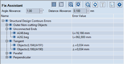
Name The object's ID. Series of objects that present errors of identical type are grouped and can be inspected by clicking the plus sign in front of the group label. For a list of the groups of errors, see the Error Type column in the table in Step 2. The objects are as follows:
| ID | Object | Note |
|---|---|---|
| A | Arc | |
| C | Circle | |
| L | Line | The extensions end and beg indicate the line's end and beginning. |
| F | Fillet | |
| Contour | An interrupted line circumscribing an area | |
| Hole | An interrupted line circumscribing an area within a closed contour | |
| Δ | The amount by which the detected object differs from the allowed value as specified in the respective allowance filter. |
Error Value The value of the error. For errors indicating linearity, the error is shown by the letter L followed by a value for the length of the object. For distance-related errors, the error is indicated by Δ, followed by the value in degrees (for angular divergence) or by length values (for linear divergence). Areas are indicated by the word Area.
- In the tabular area, inspect the listed drafting errors, and then use the respective fix option to remove the ones that will compromise the project.
IMPORTANT: In the cases that follow, error detection excludes the objects whose size is smaller than the value set in Object Size Limit.