 .
.For the successful automatic layout recovery of an imported file, it is critical that the outer contour — the continuous contour formed by the outer objects of the original layout drawing — is both closed (that is, there are no gaps in it) and in the Cutting style.
When imported into EngView , files from external formats keep their own styles and their outer contours often have gaps, which makes the recovery impossible. That is why, once you have imported a file, it is necessary to:
TIP: If all the lines in your drawing are in the same style, select by hand the objects that you want to form the outer contour, and then apply the Cutting style to them.
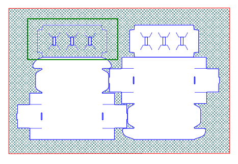
Closed contour as defined by drawing a rectangle around the original layout drawing. The fill applied to the drawn rectangle shows that the outer contour of the original drawing is closed.
The fill in the upper section of the left-hand 1up (highlighted) shows that there are gaps in this section. This means that its contour needs to be repaired.
To use automatic recovery
.The Automatic Unstructured Layout Recovery wizard appears, displaying the Unstructured layout page.
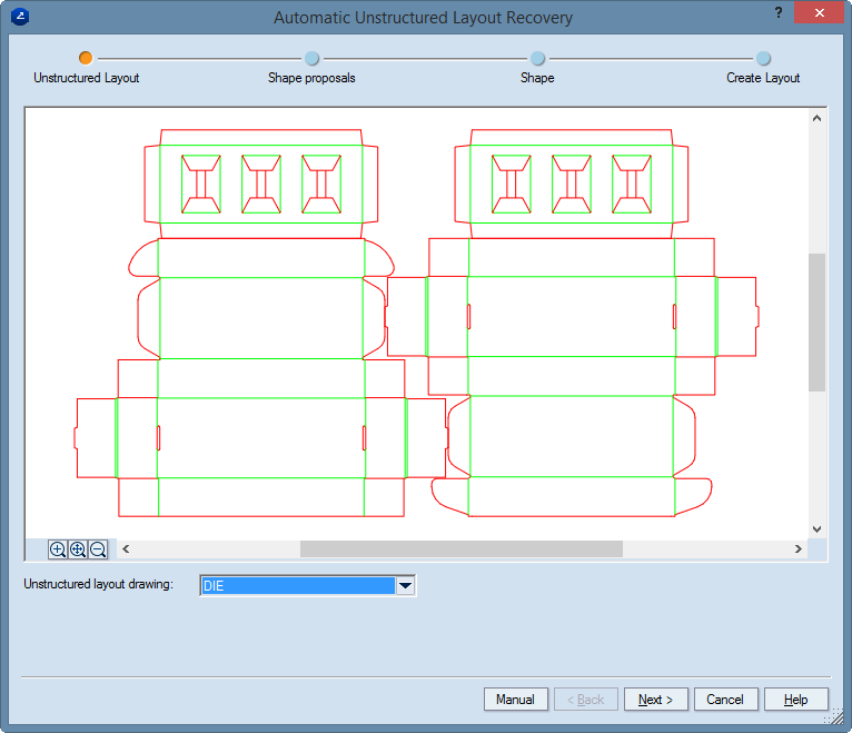
NOTE: As a result, the unstructured layout layer appears in light grey in the background of the layout drawing. It can serve as a reference drawing during the positioning of the final layout. To remove this reference drawing, in the graphical area right-click anywhere, and then click Clear Unstructured Layer on the context menu.
The Automatic Unstructured Layout Recovery wizard displays the 1Up Contours page.
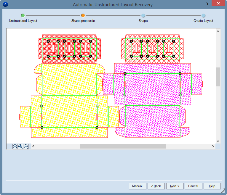
NOTE: All closed contours are initially hatched, each type in a different color. Clicking in a contour removes the hatch, thus eliminating the contour from being processed later as a layout 1up.
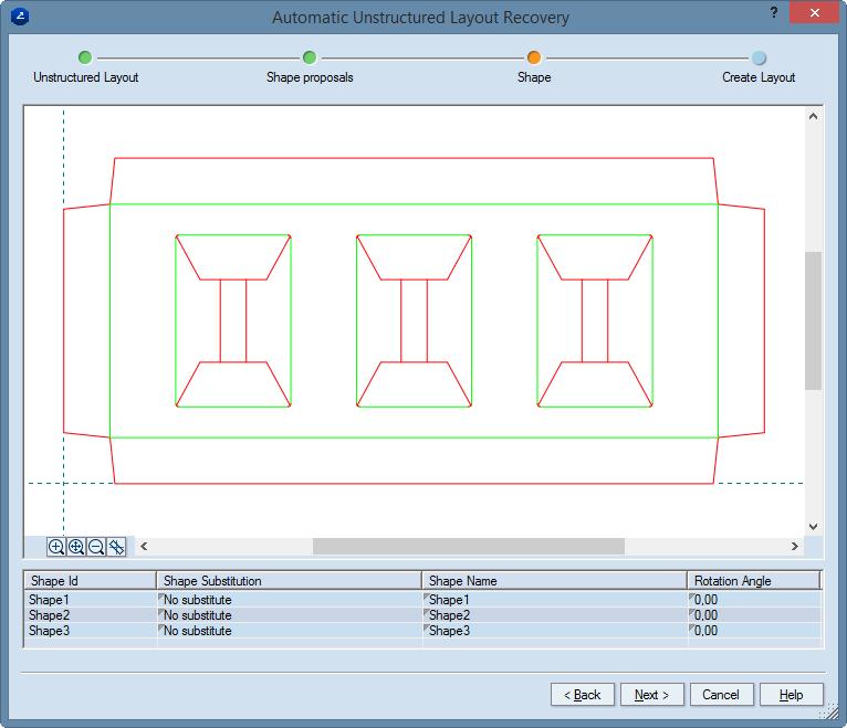
The Automatic Unstructured Layout Recovery wizard displays the 1Up Drawings page.
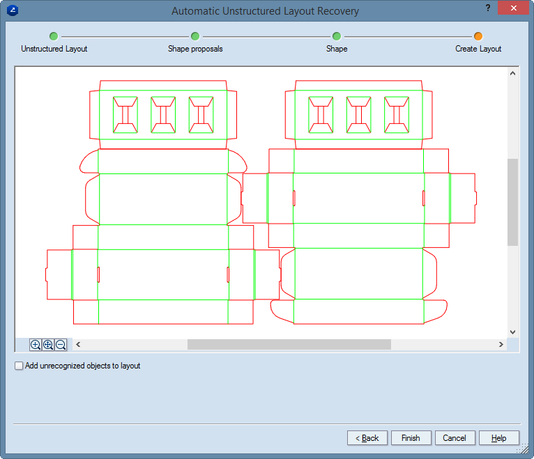
The Automatic Unstructured Layout Recovery wizard displays the Create Layout page.
NOTE: Non-1up objects can be tables, descriptions, stripping knives or markers, among others.