 .
.The most common case in creating layers manually is when we need to visualizse finishing effects.
Before applying a printing or finishing effect to an object, you must create a process layer to carry the effect. After you have created the layer, you can proceed by assigning objects in the design to the process layer. An exception are the processes backing and lamination, which are applied onto the entire design and need no specific objects.
IMPORTANT: Processes are executed in the descending order in which they appear in the Layers section — that is, the top listed layer is executed first; the bottom layer last. To rearrange the order of layers, right-click a layer, and then click Move Up/Move Down as your case requires.
NOTE: If the Layers & Objects tab is unavailable, right-click any of the available tabs, and then check Layers & Objects on the context menu.
.NOTE: To edit a layer, select it, and then click Edit Layer, or right-click the layer, and then click Edit Layer.
The New Layer dialog box appears.
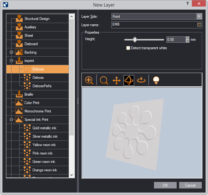
The table that follows lists (the) properties that take part in the definition of finishing effects. A property can pertain to one or multiple effects and is available only when you are defining these particular effects. You can then set the property value that works for you.
| The properties | ||
| Property | What It Does | |
|---|---|---|
| Saturation | Sets how bright you want the color to be by changing its hue. 0 produces least bright, nearly colorless surface; 100 adds most bright color. | |
| Simulate substractive color processing | Produces color by applying the rules for color mixing in the CMYK color scheme. The final color is the product of what remains of the spectrum after each layer has substracted wavelengths from the light. Selecting the check box tells Prinect to simulate this method of color mixing. | |
| Detect transparent white | If transparency is set to the white color, displays the white in accordance with the set value. | |
| Detect intensity by color | ||
| Bump height | Use the slider or the value box to set how hight you want the shape's height to be. | |
| Color | (colored neon ink only) Select a color to apply to the surface. | |
| The properties by layers | ||
| Layer | Properties | |
| Color print | Saturation; Simulate substractive color processing; Detect transparent white | |
| Monochrome print | Color; Saturation; Simulate substractive color processing; Detect transparent white | |
| Partial foil stamping | Detect transparent white; Color (Colored foil only) | |
| Special ink print | Detect intensity by colors; Color (Colored neon ink only) | |
| Varnish | Detect transparent white | |
| Imprint | Bump height; Detect transparent white | |
| Preview area controls | ||
| Icon | Name | What It Does |
 |
Fit | Fits the appearance model into the preview area. |
 |
Zoom | Starts zooming inside the preview area. |
| Pan | Starts moving the appearance model across the preview area. | |
 |
Turn | Starts rotating the appearance model within the preview area. |
 |
Single Axis Rotation | Starts rotating the appearance model along the axis defined by how you move the mouse. |
 |
View Options | Opens a dialog box in which you can set the lighting of the preview area. |
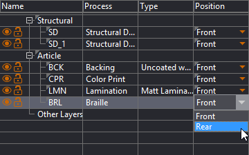
TIP: You can change the position of a process layer directly in the tabular area while working on the design.