The Dimensions dialog box appears.
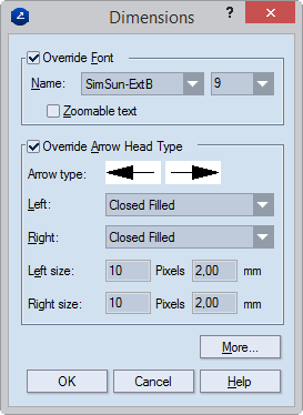
Override Font Enables editing of the properties in the area.
Name Sets the font which will be used for displaying the text of the dimension values in the graphical pane.
(Size) Sets the font size.
Zoomable Zooms the dimension text together with the 1up drawing in the graphical pane. When unselected (the default state), the text is always displayed with the font size that is assigned to the dimension, regardless of whether you are zooming the 1up.
Text format Sets the way the dimension-line text will be displayed in the graphical pane. Unavailable, except when invoked from resizable template drawings (.evr files).
Override Arrow Head Type Enables the editing of the properties in the area.
Sample Displays a sample image of the arrows as they will appear in the graphical pane.
Left Sets the appearance of the left arrow of the dimension line. The list contains a set of predefined arrow types. When you select an arrow type, its sample is displayed in Sample.
Right Sets the appearance of the right arrow of the dimension line. The list contains a set of predefined arrow types. When you select an arrow type, its sample is displayed in Sample.
Left size:
Pixels Sets the size, in pixels, of the left arrow head. NOTE: This value applies only to how the selected dimension line will appear on the screen in 1up, layout or print drawings. It does not apply to how dimension lines will appear when printed.
mm [cm/dm/inch/feet] Sets the size of the left arrow head when printed. NOTE: Changing the value in this edit box does not appear on the screen.
Arrow size:
Pixels Sets the size, in pixels, of the right arrow head. NOTE: This value applies only to how the selected dimension line will appear on the screen in 1up, layout or print drawings. It does not apply to how dimension lines will appear when printed.
mm [cm/dm/inch/feet] Sets the actual size of the left arrow. Changes in this edit box are not visualized on the screen; however, the value sets the arrow size of the selected dimension lines in printing.
The More Dimensions Options dialog box appears.
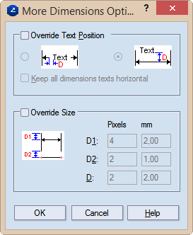
Text Position Sets the position of the text of the dimension line. NOTE: Selecting the left-hand option places the text in the middle of the dimension line; selecting the right-hand option places the text above the line.
Keep all dimension texts horizontal Makes dimension texts appear horizontal. For vertical dimension lines, the figures of the value cross the dimension line. You can use the mouse to drag the figures along the line and position the them where you want them to be.
Override Size Sets the size of the dimension indications.
D1: Pixels Sets the span, in pixels, between the dimension line and the ends of the dimension border lines. NOTE: This value applies only to how the selected dimension line will appear on the screen in 1up, layout or print drawings. It does not apply to how dimension lines will appear when printed.
D1 mm Sets the actual span, in metric units, between the dimension line and the ends of the dimension border lines. Changes in this edit box are not visualized on the screen; however, value sets the span between the dimension line and the ends of the dimension border line in printing.
D2: Pixels Sets the span, in pixels, of the blank intervals between the objects that are being dimensioned and the beginnings of the dimension border lines. NOTE: This value applies only to how the selected dimension line will appear on the screen in 1up, layout or print drawings. It does not apply to how dimension lines will appear when printed.
D2 mm Sets the actual span, in metric units, of the empty distances between the objects that are being dimensioned and the beginnings of the dimension border lines. Changes in this edit box are not visualized on the screen; however, its value defines the span of the blank intervals between the objects that are being dimensioned and the beginnings of the dimension border lines in printing.
D: Pixels Sets the span, in pixels, of the empty distances between the dimension line and the text. This value applies to the way the selected dimension lines are displayed on the screen in the 1up, layout or print drawings. It does not affect the actual appearance of the selected dimension line in printing.
If in the Text Position area you have clicked the left option, these are the two empty distances between the text and the dimension line ends to the right and left sides of the text. Alternatively, the empty distance is between the dimension line and the text above it.
D mm Sets the span, in metric units, of the empty distances between the dimension line and the text. These changes are not visualized on the screen; however, the value sets the empty distances between the dimension line and the text in printing.
If in the Text Position area you have clicked the left option, these are the two empty distances between the text and the dimension line ends to the right and left sides of the text. Alternatively, the empty distance is between the dimension line and the text above it.
Notes