 .
.Design frames require special areas in which to hold the drawings. 1ups, layout 1ups and 3D drawings. These areas serve as placeholders in which the respective drawings — 1up, layout, 3D — fit while a print presentation is being created.
TIP: If in a print drawing you apply a design frame that has more predefined areas than the number of drawings in the project, some areas in the print drawing will remain empty. For example, if you apply a design frame that has three 1up areas but your project has only two 1up drawings — in this case one area will remain empty. When you click the frame, warnings appear at the empty areas in the print drawing to indicate the predefined but unused areas.
To define drawing areas in a design frame
NOTE: You can create a design frame even while you are working on an specific project.
An empty drawing opens.
.A contextual edit bar appears above the graphical area.

The Design Frame Part Properties dialog box appears.
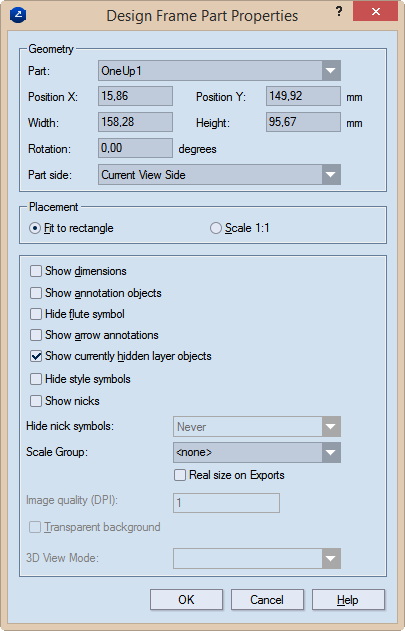
Geometry Settings for the part's size and position
Part Sets the part type (1up, layout, 3D) to be inserted by default in the current rectangular area when you use the design frame to create a print drawing.
Position X Sets the position of the part along the x-axis.
Position Y Sets the position of the part along the y-axis.
Width Sets how wide the rectangular area will be.
Height Sets how tall the rectangular area will be.
Rotation Sets the angle at which the part will be rotated in the rectangular area.
Part side (1up and layout drawings only) Sets the side that will be displayed in the rectangular area. The options are: Current View Side, Front, Rear, Diecutting, Counterdiecutting.
Placement Sets if the part will be scaled to fit the area or will be placed in 1:1 ratio.
Fit to rectangle Makes the part fit into the positioning rectangle in the design frame. TIP: If you will use a scale group (see below), select this option.
Scale 1:1 Places the part without scaling.
Show dimensions Makes visible, in the printed document, the dimensions in the 1up and/or layout drawings.
Show annotation objects Makes visible, in the printed document, any notes added to the 1up drawing and part of the Annotations layer.
Hide flute symbol Does not display, in the printed document, the symbol that indicates the direction of the flute or grain.
Show arrow annotations Displays the arrow annotations. NOTE: The Show annotation objects check box must also be selected.
Show currently hidden layer objects Makes visible, in the printed document, layer objects that have been added to the 1up but were made invisible — for example, to declutter the view.
Hide style symbols The printed drawing will not display any style symbols added to it and visible in the graphical area.
Show nicks Displays nicks if any have been placed into a 1up.
Hide nick symbols Settings for whether nick symbols will be displayed in the print drawing. The options are Always (nick symbols are never displayed); Never (nick symbols are always displayed); If all nicks share a width (nick symbols are NOT displayed only if ALL the nicks in the drawing have the same width).
Scale Group The name of the scale group that you want to assign to the print drawing part. The scaling applied to the largest part in the group will be applied to all grouped parts.
TIP: For new groups, type a name; for existing groups, select a name from the drop-down list.
IMPORTANT: To use the Scale Group functionality, ensure that in Placement you have selected the Fit to rectangle option.
PDF export in real size Select this check box to export the print drawing in its actual size as a PDF file. "In actual size" means that the exported drawing will not be scaled down to fit a predefined media size such as A3, A4 or other. In other words, if your drawing's size is for example, 1500 mm x 2000 mm, the exported PDF drawing will keep these measurements, without scaling them down.
TIP: The functionality is linked to the use of the Scale Group functionality. If you choose not to use a scale group, only the uppermost drawing in the Name Mapping list will be exported in actual size, regardless of whether you set the real-size export also to the rest of the drawings. To export all the drawings in the project in their actual sizes, add them to a scale group. To learn how, see the Scale Group guidance above.
IMPORTANT: The PDF file format has a standard limitation of 200 inches x 200 inches (appr. 5 meters x 5 meters) for displaying a document. If the actual measurements of the exported drawing are larger than these values, the PDF document will cut the exported drawing to meet this limitation.
Image quality (DPI) (Available when the 3D drawing is selected in the table) Sets the graphic quality of the 3D image.
Transparent background Makes transparent the background of the 3D area. This allows the 3D area to appear in the color set as background for the graphical area. The functionality is especially useful for white-colored 3D models: Changing the color of the drawing area background makes white-colored 3D models stand out against it.
3D View Mode Sets how the 3D model will be displayed in the print drawing. The options are: Solid (untransparent panels), Transparent (see-through panels), Wireframe (see-through panels and grey edge outlines) and Solid B&W (white untransparent panels and black edges).
Notes