 to set how the draw marker will appear on the screen. After you have set
the properties, in the read-only field you will see the chosen style name;
in the white field you will see the chosen pattern.
to set how the draw marker will appear on the screen. After you have set
the properties, in the read-only field you will see the chosen style name;
in the white field you will see the chosen pattern.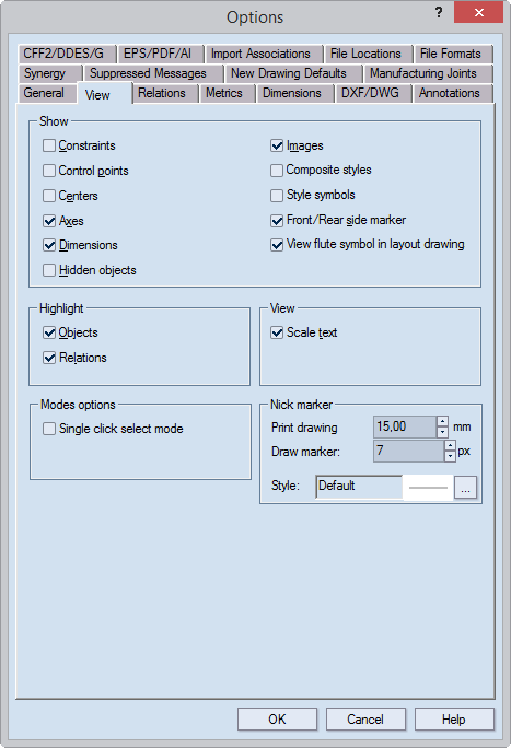
Show Sets the attributes that will appear on the screen. NOTE: Apart from the commands Dimensions and View flute symbols in layout drawings, the commands in the Show section produce identical effects as the commands that you find when you double-click in the graphical area, and then point to Show.
Constraints Displays the constraints in the drawings of projects you open or create.
Control points Displays the control points in the drawings of projects you open or create.
Centers Displays the center points of arcs and circles in the drawings of projects you open or create.
Axes Displays the coordinate axes in the drawings of projects you open or create.
Dimensions Displays the dimensions in the drawings of projects you open or create.
Hidden objects Displays the hidden objects in the drawings of projects you open or create.
Images Displays the images in the drawings of projects you open or create.
Composite styles Displays how composite styles actually appear when applied to the media.
Style symbols Displays the marks (images) that designate the styles when the drawing is viewed on the screen or is printed. NOTE: The use of style symbols is optional. Learn how to designate marks to styles.
Front/Rear side marker Displays the Print/Rear side marker, which indicates if the design is facing its print or die side. To change the design orientation, in the graphical area right-click, point to Show, and then ensure that View Front Side is not checked.
View flute symbol in layout drawings When this check box is selected, the flute/grain symbol appears in layout 1ups. NOTES:
Highlight Sets the attributes that will be highlighted on the screen.
Objects Enables highlighting of objects (including dimensions) when you point to them in the graphical area.
Relations Enables highlighting of objects for which relations are detected when, in an object-drawing mode, you point to them in the graphical area.
View Sets the behavior of certain features.
Scale text Scales any text objects in print drawings that originate from the source 1up drawing along with the whole print/design part in the drawing according to the part's scale coefficient. NOTE: When you use a design frame, the included parts are scaled and fit the predefined rectangular areas in the design frame. We recommend text scaling when in the original 1ups you work with large text strings.
Modes options An option for setting how the selection rectangle is defined
Single click select mode When this check box is selected, defining the rectangle that encompasses the object to select is done by two clicks: (1) Click, (2) drag and (3) release, whereupon the selection is done. Learn more about the two rectangle-defining techniques.
Nick marker Properties setting the visualization of nicks in 1ups and print drawings
Print drawing Type a value for how long you want nicks to appears in print drawings.
Draw marker (Visualization purposes only. Size in pixels.) The minimum size that the nick will have on the screen. For example, when you start zooming out and the nick size becomes smaller than the value set here, the nick is visualized by a substitute draw marker. In Style, set a style for the draw marker.
Style Click the browse button
to set how the draw marker will appear on the screen. After you have set
the properties, in the read-only field you will see the chosen style name;
in the white field you will see the chosen pattern.