You can set overall properties for an individual
drawing regarding the material, its type and appearance.
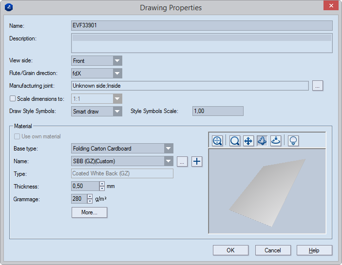
| Name |
Sets the name of the drawing. |
| Description |
(Optional) Notes describing the drawing. |
| View Side |
Sets the design side that you will view in the graphical area. |
| Flute/Grain Direction |
Sets the direction — along the x- or the y-axis — of the flute
(or grain) of the material. |
| Manufacturing Joint |
Loads the manufacturing
joint preset for the structure, if such a property has been
set for the structure.  Click to select or reset
the structure's manufacturing joints.
Click to select or reset
the structure's manufacturing joints.
HOW TO USE: Set a manufacturing joint if (1) EngView is
integrated with an external production system that requires information
about the joint or (2) you want to create an editable source structure;
by editing the manufacturing joint, you use the structure to which
it is applied to effectively construct a different design. |
| Scale dimensions to |
Not selected by default. Sets how EngView scales
dimensions while exporting
or printing
out the drawing. The options are 1:1 (WYSIWYG) or a custom
pattern. If you need a different pattern, select the check box,
and then define a custom
scaling pattern.
- If a global scaling patterns has been defined, it appears
here; if not, you can set one here.
- Ensure that the scaling pattern corresponds to the paper
size that you want to use. For example, if you want to use
an A4 Landscape paper, set
a 210X297 pattern.
|
| Draw Style Symbols |
Sets how style symbols appear
on the screen in the drawing. |
| Style Symbols Scale |
Sets a scale factor that EngView will
apply for reproducing style symbols on the screen, on print and
exported drawings. Example: If a style symbol is 16x16 pixels
and the scale factor is 2.00, the symbol size will be displayed
twice as large on the screen. |
| |
| Material |
Settings that define the material used for the design in the
drawing |
| Use own material |
Overrides the material set
for the whole project and allows the use of another one for
the current drawing.
NOTE: If the check box is unavailable, this means
that a specific material has been set for the whole project. If
you want to change the material of specific drawings, (1) enable
the use of different materials in the project, and then (2)
select the check box here, and then set a material for the active
drawing. |
| Base type |
Sets the parent material type for the current material. |
| Name |
Sets the material for the drawing. To select a different material,
click the browse button ,
and then, in the dialog box that appears, select a material.
 Opens a dialog box in which you can add
a material to the catalog. Opens a dialog box in which you can add
a material to the catalog.
|
| Type |
Read-only. Displays the subtype
on which the material is based. |
| Thickness |
Sets the thickness value that EngView uses
for its calculations within resizable templates. (In parameter
expressions, this is the value represented by the d()
function.) By default, the value is inherited from that of
the parent material type.
|
Case 1: To change the value along with that in
Calc. thickness, select the left check box. When you change
the value in Calc. thickness, the value in Real thickness
changes too.
Case 2: To set a value that is different from that
in Calc. thickness, select both check boxes, and then type
a new value. The value in Calc. thickness is not affected.
Clearing the right check box restores the value in Calc. thickness;
clearing both check boxes restores the value set for the parent
type. |
| Grammage |
Sets the weight, in grams per square meter, for the material. |
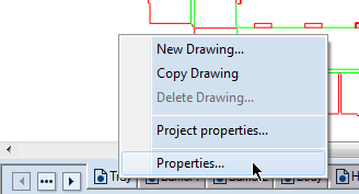
| More |
Opens a dialog box in which you can set further properties
for the drawing (see Step 3). |
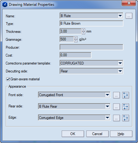
| Name |
Sets a material. Use the drop-down list to select a material,
or click the browse button to add a material that is not on the
list. |
| Type |
Read-only. Displays the material type on which the material
selected in Name is based. |
| Thickness |
Sets the thickness value that EngView uses
for its calculations within resizable templates. (In parameter
expressions, this is the value represented by the d()
function.) By default, the value is inherited from that of
the parent material type. To change the inherited value, select
the check box, and then type the new value.
Clearing the check box restores the value set for the parent type.
|
|
| Grammage |
Sets the weight, in grams per square meter, for the material. |
| Producer |
The producer name |
| Cost |
Sets a cost for the material. |
| Description |
Additional information about the material |
| Comment |
Notes about the material |
| Corrections parameters template |
Applies the parameter
template that will be used in the operations in which the
material will be used. |
| Diecutting side |
Indicates the side on which the cutting die falls. |
| Grain-aware material |
Indicates the fiber direction in material texture. |
| |
| Appearance |
Settings for attaching surfaces to the material's front
and rear sides and the edge |
|
Opens a dialog box in which you can select a surface appearance. |
 |
Opens a dialog box in which you can edit the selected surface: its
the colors,
texture, and bump. |