


You can set overall properties for a packaging project that concern the material, its type and appearance. You can distinguish between the properties of the separate drawings for which you can set specific properties.
To set project properties
The Project Properties dialog box appears.
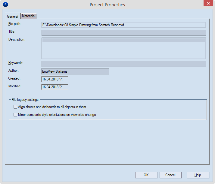
| File Name | Displays the location of the file (read-only) |
|---|---|
| Title | The name of the project |
| Description | Notes about project |
| Keywords | A field for words by which the project can be indexed. |
| Author | A field for the creator of the project. |
| Created | Displays the date on which the project was started (read-only). |
| Modified | Displays when the project was last saved (read-only). |
| File Legacy Settings | Displays the date on which the project was started (read-only). |
| Align sheets and dieboards to all objects in them | When the check box is empty (the default state), sheets and dieboards are positioned (centered) by taking into account only objects in production-related styles — for example, Cutting, Creasing, Perforating, Half-Cut, Cut-Crease. When the check box is selected, the positioning takes place by taking into account all objects within the sheet or dieboard regardless of what styles they are in. |
| Mirror composite style orientations on view-side change | Select this check box only when you are working with files created with a version earlier than 6.4.35. The functionality mirrors the orientation of composite style when you switch the view side from front to rear or vice versa. Selecting the check box suppresses a version 6.4.35-introduced technology for working with composite styles and reverts to the earlier technology. This throwback applies only to the current project. When you select the check box, EngView correctly visualizes the composite styles created with versions earlier than 6.4.35. When you load such a file, EngView selects the check box automatically and notifies you that composite styles were created with an earlier version of profile visualization, which still applies to this file. |
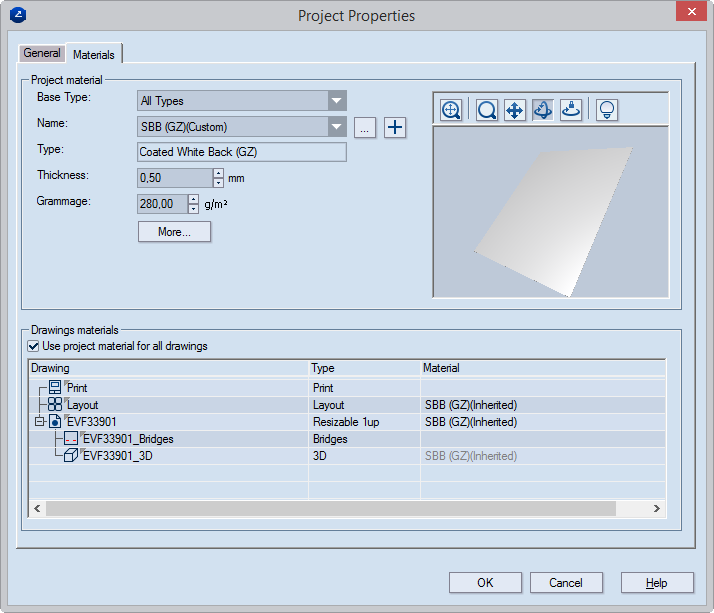
| Project material | Sdflhdlfkgsdlkj |
|---|---|
| Base Type | Sets the material type on which the material is based. |
| Name | Sets the material for the project. To select a different material, click the browse button, and then, in the dialog box that appears, select a material. Opens a dialog box in which you can add the material to the material catalog for future use. |
| More | Opens a dialog box in which you can set additional properties for the material. |
| Type | Read-only. Displays the subtype on which the material is based. |
| Thickness | Sets the thickness value that EngView uses
for its calculations within resizable templates. (In parameter
expressions, this is the value represented by the d()
function.) By default, the value is inherited from that of
the parent material type. To change the inherited value, select
the check box, and then type the new value. Clearing the check box restores the value set for the parent type. |
|
| Grammage | Sets the weight, in grams per square meter, for the material. |
| Icon | Control Name | What It Does |
|---|---|---|
|
Fit | Makes the surface model fit the preview area. |
|
Zoom | Click to begin zooming inside the preview area. |
|
Pan | Click to start moving the surface model across the preview area. |
|
Turn | Click to start rotating the surface sample within the preview area. |
|
Single Axis Rotation | Click to begin rotating the surface model along the axis defined by the movement of the mouse. |
|
Set scene | Opens a dialog box in which you can set the lighting of the preview area. |
|
Snapshot Icon | Makes a snapshot of the surface model in the preview area. This snapshot then automatically appears as an icon for the surface appearance in the catalog list. |
| Drawings materials | |
|---|---|
| Use project material for all drawings | Select this check box to use the selected material in all the drawings of the project. Clear the check box if you want to use individual materials for the drawings in the project. |
| THE TABLE | |
| Drawing | A list of the drawings in the project |
| Type | What kind of drawing it is. |
| Material | The material set for the drawing. NOTE: You can set separate material for each drawing:
Double-click the |
The Drawing Material Properties dialog box appears.
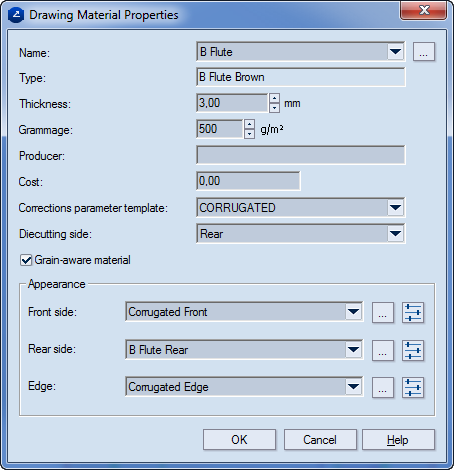
| Name | Sets a material. Use the drop-down list to select a material, or click the browse button to add a material that is not on the list. |
|---|---|
| Type | Read-only. Displays the material type on which the material selected in Name is based. |
| Thickness | Sets the thickness value that EngView uses
for its calculations within resizable templates. (In parameter
expressions, this is the value represented by the d()
function.) By default, the value is inherited from that of
the parent material type. To change the inherited value, select
the check box, and then type the new value. Clearing the check box restores the value set for the parent type. |
|
| Grammage | Sets the weight, in grams per square meter, for the material. |
| Producer | The producer name |
| Cost | Sets a cost for the material. |
| Description | Additional information about the material |
| Comment | Notes about the material |
| Corrections parameters template | Applies the parameter template that will be used in the operations in which the material will be used. |
| Diecutting side | Indicates the side on which the cutting die falls. |
| Grain-aware material | Indicates the fiber direction in material texture. |
| Appearance | Settings for attaching appearances to the material's front and rear sides and the edge |
 |
Opens a dialog box in which you can select a surface appearance. |
 |
Opens a dialog box in which you can edit selected surface appearance: the colors, texture, and bump. |
 -marked
rows, and then select a material from the list that appears.
-marked
rows, and then select a material from the list that appears.