Print drawing with 1up and layout drawings
Print drawing with 1up and 3D drawings
A print drawing is where you position your design frames. In a print drawing you can draw all types of geometric objects, make transformations to them, set dimensions and insert design frames, 1ups and layout 1ups. You can begin creating a new print drawing from any active drawing: 1up, layout, CAM, 3D Fold or another print drawing.
|
|
|
|
Print drawing with 1up and layout drawings |
Print drawing with 1up and 3D drawings |
 .
.The Print Frame Placement dialog box appears in the Select Print Frame step.
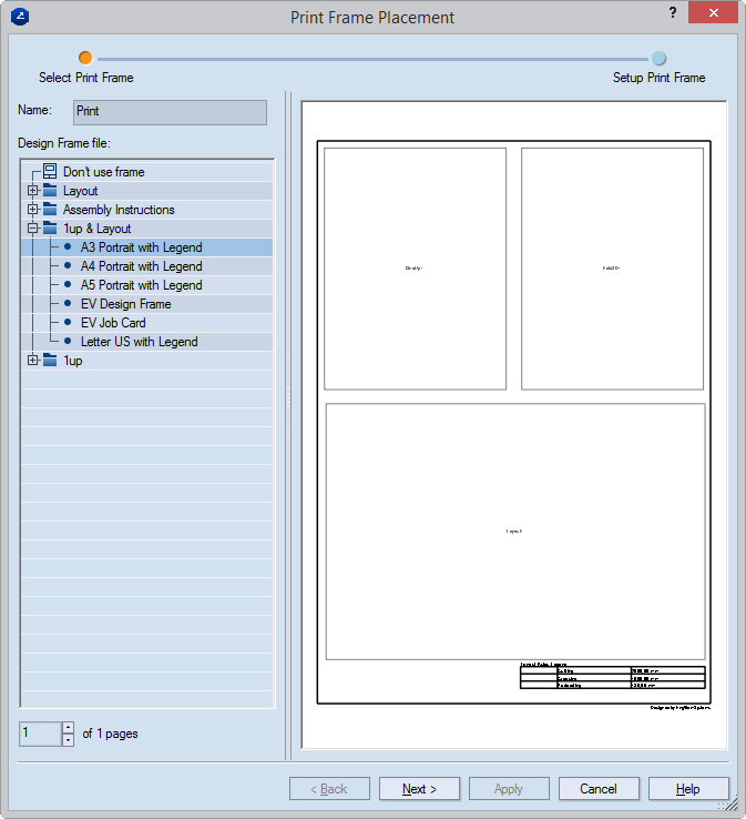
NOTE: The list you see in the dialog box follows the structure of the directory of your installation that contains the design frames — C:\EngViewWork7\Settings\DESIGN FRAMES. This means that if you arrange design frames in different folders within the DESIGN FRAMES folder, the respective folders will appear in the list. You can then browse the folders and select the design frame that you need.
IMPORTANT: When arranging design frames in folders, make sure these folders are always subfolders of the DESIGN FRAMES directory.
NOTE: You can set a page number here only if you already have at least one print drawing and are in the process of creating another. Understandably, you cannot assign a number greater than the total number of pages — that includes the one you are creating at the moment — but you can assign to the drawing being created any number lower than the total number of drawings; the number sequence will update automatically.
The Print Frame Placement dialog box appears in the Setup Print Frame step.
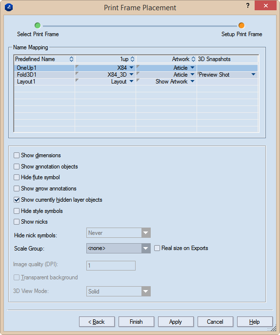
Predefined name Lists the names of all predefined rectangular areas which have been incorporated in the selected design frame.
1up Lists the 1ups/layout/3D/bridges drawings to be placed in the respective predefined rectangular areas. Each column field is a list. To assign a drawing to a predefined rectangular area, click in the respective field to open the list, and then select the drawing that you want.
Artwork The article applied onto the 1up or the 3D model.
3D Snapshots Lists the names of the available 3D shots. To assign a snapshot, click the respective field to open the list, and then select the one you want. Available only if a 3D drawing is selected in the corresponding 1up column field.
Show dimensions Makes visible, in the printed document, the dimensions set in the drawing.
Show annotation objects Makes visible, in the printed document, any notes added to the respective drawing and assigned to the Annotations layer.
IMPORTANT: Select this check box if you want to see arrow annotations (see below).
Hide flute symbol Does not display, in the printed document, the symbol that indicates the direction of the flute or grain.
Show arrow annotations Displays the arrow annotations.
IMPORTANT: The Show annotation objects check box (see above) must also be selected.
Show currently hidden layer objects Makes visible, in the printed document, layer objects that have been added to the 1up but were made invisible — for example, to unclutter the view.
Hide style symbols The print drawing will not display style symbols (if any have been added to the underlying drawing).
Show nicks Displays the nicks, if any have been placed into the 1up.
Hide nick symbols Settings for whether nick symbols will be displayed in the print drawing. The options are Always (nick symbols are never displayed); Never (nick symbols are always displayed); If all nicks share a width Consider two cases: (1) If the nicks in the drawing are of the same width, the symbols will not be displayed. (2) If the nicks are of different widths, the program displays only the symbols of the nicks whose number is fewer than 75% of the total number of nicks. In other words, if there are same-width nicks whose number is equal to or greater than 75%, their symbols will not be displayed.
Scale Group The name of the scale group that you want to assign to the print drawing part. The scaling applied to the largest part in the group will be applied to all grouped parts. This functionality is handy if you want to visualize the parts in a multipart structure and keep the proportion between them.
IMPORTANT: For the Scale Group functionality to work properly, ensure that the Fit to rectangle option is selected in the Placement area of the structure of the frame you are using. To check this, begin editing the frame.
TIP: For new groups, type a name; for existing groups, select a name from the drop-down list.
PDF export in real size Select this check box to export the print drawing in its actual size as a PDF file. "In actual size" means that the exported drawing will not be scaled down to fit a predefined media size such as A3, A4 or other. In other words, if your drawing's size is for example, 1500 mm x 2000 mm, the exported PDF drawing will keep these measurements, without scaling them down.
TIP: The functionality is linked to the use of the Scale Group functionality. If you choose not to use a scale group, only the uppermost drawing in the Name Mapping list will be exported in actual size, regardless of whether you set the real-size export also to the rest of the drawings. To export all the drawings in the project in their actual sizes, add them to a scale group. To learn how, see the Scale Group guidance above.
IMPORTANT: The PDF file format has a standard limitation of 200 inches x 200 inches (appr. 5 meters x 5 meters) for displaying a document. If the actual measurements of the exported drawing are larger than these values, the PDF document will cut the exported drawing to meet this limitation.
Image quality (DPI) (Available when the 3D drawing is selected in the table) Sets the graphic quality of the 3D image.
Transparent background Makes transparent the background of the 3D area. This allows the 3D area to appear in the color set as background for the graphical area. The functionality is especially useful for white-colored 3D models: Changing the color of the drawing area background makes white-colored 3D models stand out against it.
3D View Mode Sets how the 3D model will be displayed in the print drawing. The options are: Solid (nontransparent panels), Transparent (see-through panels), Wireframe (see-through panels and grey edges) and Solid B&W (white nontransparent panels and black edges).
NOTE: A special case exists when in the print drawing you want to refer to external objects and want to apply formulas about them.
Notes