You can edit rectangular areas to alter the parts which will fit in them, the types of parts which will fit in them, the size and position of the areas on the design frame, as well as the scaling of the parts.
To edit a design frame
The design frame drawing appears as a separate project.
The Design Frame Part Properties dialog box appears.
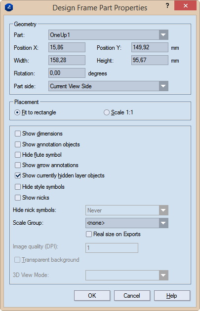
Geometry Settings for the part's size and position
Part Sets the part type (1up, layout, 3D) to be inserted by default in the current rectangular area when you use the design frame to create a print drawing.
Position X Sets the position of the part along the x-axis.
Position Y Sets the position of the part along the y-axis.
Width Sets how wide the rectangular area will be.
Height Sets how tall the rectangular area will be.
Rotation Sets the angle at which the part will be rotated in the rectangular area.
Part side (1up and layout drawings only) Sets the side that will be displayed in the rectangular area. The options are: Current View Side, Front, Rear, Diecutting, Counterdiecutting.
Placement Sets specifics of how the part is placed onto the
Fit to rectangle Makes the part fit into the positioning rectangle in the design frame.
Scale 1:1 Places the part without scaling.
Show dimensions Makes visible, in the printed document, the dimensions set in the drawing.
Show annotation objects Makes visible, in the printed document, any notes added to the respective drawing and assigned to the Annotations layer.
IMPORTANT: Select this check box if you want to see arrow annotations (see below).
Hide flute symbol Does not display, in the printed document, the symbol that indicates the direction of the flute or grain.
Show arrow annotations Displays the arrow annotations.
IMPORTANT: The Show annotation objects check box (see above) must also be selected.
Show currently hidden layer objects Makes visible, in the printed document, layer objects that have been added to the 1up but were made invisible — for example, to unclutter the view.
Hide style symbols The print drawing will not display style symbols (if any have been added to the underlying drawing).
Show nicks Displays the nicks, if any have been placed into the 1up.
Hide nick symbols Settings for whether nick symbols will be displayed in the print drawing. The options are Always (nick symbols are never displayed); Never (nick symbols are always displayed); If all nicks share a width Consider two cases: (1) If the nicks in the drawing are of the same width, the symbols will not be displayed. (2) If the nicks are of different widths, the program displays only the symbols of the nicks whose number is fewer than 75% of the total number of nicks. In other words, if there are same-width nicks whose number is equal to or greater than 75%, their symbols will not be displayed.
Scale Group The name of the scale group that you want to assign to the print drawing part. The scaling applied to the largest part in the group will be applied to all grouped parts. This functionality is handy if you want to visualize the parts in a multipart structure and keep the proportion between them.
IMPORTANT: For the Scale Group functionality to work properly, ensure that the Fit to rectangle option is selected in the Placement area of the structure of the frame you are using. To check this, begin editing the frame.
TIP: For new groups, type a name; for existing groups, select a name from the drop-down list.
Image quality (DPI) (Available when the 3D drawing is selected in the table) Sets the graphic quality of the 3D image.
Transparent background Makes transparent the background of the 3D area. This allows the 3D area to appear in the color set as background for the graphical area. The functionality is especially useful for white-colored 3D models: Changing the color of the drawing area background makes white-colored 3D models stand out against it.
3D View Mode Sets how the 3D model will be displayed in the print drawing. The options are: Solid (nontransparent panels), Transparent (see-through panels), Wireframe (see-through panels and grey edges) and Solid B&W (white nontransparent panels and black edges).
NOTE: Learn more about the types, syntax and functions of predefined formulas that you can include in a design frames.