Creating, editing global styles
- On the Format menu, click Global Styles.
The Global Styles
dialog box appears.

- Click New.
The New Style dialog box appears.

| Style name |
Type a name for the new style. |
| Parent style |
Select a parent style — that is, the style whose properties
will serve as a basis for the new style. If you want the new style
to have no parent (first-level style), select None. |
| Type |
Available when None is selected in Parent style
and can have one of the four style types: Flat, which has no structure;
and Perforating, CutCrease and Composite, all of which have structure
(see later in this topic). Select a style type and type a name
in Style name. The style you thus define is a first-level
style that can be a parent style. |
- In the dialog, enter the values that you need, and then click OK.
- In the Global Styles dialog
box, select the style you have just created.

| Style name list |
Lists all system and user-created global styles. Select the
style you want to edit, and inspect its properties in the tabs
on the right-hand side. |
| New |
Opens a dialog box in which you begin to create a new global
style. |
| Delete |
Deletes the style selected in the list.
NOTE: You can delete only user-defined styles. |
| Style name |
Sets the name of the style. Available only for user-created
styles. |
| Use in new blank projects and imports |
Makes the style available in new blank
projects or projects that originate
from imported files.
NOTE: Styles not set as default need to be added
manually to projects. |
| Description |
(Optional) Add notes about the style. |
| Use in print legend |
Specifies how the lengths of objects in this style will be
listed in design frame
legends. The options are:
|
The Visual tab
The properties in this tab set how styles appear on the screen.

| Color |
Sets a color for objects.
TIP: When you have modified the color of a parent
style, to see its child styles in the same color, collapse and
then expand either of the parent's adjacent styles. |
| Line width |
Sets how wide (in pixels) a line or curve will appear. The
value applies to objects in 1up, layout, print, CAM and 3D drawings;
it does not affect line width in printing jobs and in the generation
of tool path for CAM jobs.
NOTE FOR COMPOSITE STYLES: EngView uses
the line width set here also for composite styles, if you have
opted not to view the actual
pattern of composite styles. |
| Point size |
Points only. Sets how large points
drawn in the selected style will appear. Value range: 0.10
– 15.00. |
| Pattern |
Sets the pattern in which objects in the style will appear
in 1up, layout, print, CAM and 3D drawings. The dropdown list
contains predefined patterns and an option (Custom...)
for creating custom patterns.
The second box sets the actual line width in points. Changes
in this edit box are not visible on the screen; the value sets
the line width of objects in the selected style in printing jobs
and for the generation of tool path for CAM jobs (see the following
note).
NOTE FOR USE IN CAM: The value is important for
toolpath generation: If the width of the respective CAM tool is
narrower than the line width specified here, a different tool
path may be generated, involving, for instance, the offsetting
of wide lines for the cutting tool (for changes of the line width
settings of a style associated with the cutting tool).
CUSTOM PATTERN: You can create a custom pattern: Scroll to the
bottom of the list, and then click Custom. Then, in the
dialog box that appears, clear some black rectangles to create
the pattern that you need, and then also set the line width.
 |
| Symbol |
Read-only. Symbol is the mark set to indicate the style when
listed in a legend.
NOTE ON APPLYING SYMBOL IMAGES: Optimal screen
view of the style symbols is achieved when the height and width
of images are 60 pixels x 60 pixels. This guarantees that printing
the symbols at 300 dpi will produce a symbol size of 5 mm x 5
mm, ensuring distinct and clear appearance. The style symbol is
always visible — if, for constructional purposes, a section of
an object is hidden from view, the symbol reappears on the visible
sections of the object.
NOTES ON VIEWING SYMBOLS: To view style symbols properly:
- Select the right zoom factor so the length of the image
used for the style symbol is shorter than the length of
the object. On the screen, style symbols will disappear
when a drawing is zoomed out, which causes objects to
appear smaller.
- To view style symbols, in the graphical area, right-click,
point to Show, and then check View style symbols.
|
| Viewing depth |
Sets the stack order of a style. If multiple objects in different
styles overlap, the object in the style with the greatest stack
order is visible on the screen. The others are not visible regardless
of when each object was drawn. Value range: –1.00 to 1.00.
EXAMPLE STYLES: If the Cutting style has a stack
order of 0.5 and the Axis style has a stack order of –0.4, when
objects in the two styles overlap, the one in the Cutting style
will always be visible and the one in the Axis style will never
be visible.
EXAMPLE SELECTIONS: The functionality applies also
to selections. For overlapping objects, the object in a style
with a greater stack order is always visible even if the object
in a style with a lower stack order is selected. If objects in
styles with the same stack order overlap, you see the one that
is selected. |
The Production
tab
The properties in this tab set the actual, physical properties of objects
in the style as they should be processed in production.

| Line width |
Sets, in points, the physical thickness of objects.
NOTE FOR COMPOSITE STYLES: The line width set here
applies to printing or exporting jobs if you have opted not to
view the actual
pattern of composite styles. |
| Production process |
Defines the technology that will be used for processing objects
in the style. See a list
of the available production processes. |
| Bevel cut angle |
Available when the Bevel Cut process is selected in Production
process. Sets the angle at which bevel cut will process the
media. |
| Tool type |
Used for integration with external systems whose production
processes may require additional information (tool type) to distinguish
between different tools for production. (The Creasing Wheel process
is an example.) You can thus use the Tool Type property to define
two styles with different production processes. When such a process
is selected in Production process, the field becomes available,
and you can set a number in it.
EXAMPLE: You can define two Wheel Creasing styles
(Wheel Creasing 1 and Wheel Creasing 2) that will
serve two creasing wheel production processes. Wheel Creasing
1 will have production process Creasing Wheel (tool
type 1), Wheel Creasing 2 will have production process Creasing
Wheel (tool type 2).
The Tool Type property plays no role in processes not related to
production: Auxiliary, Panel Separator, Glue Area Contour, and
Closed Area Contour. |
The Structure
tab: Perforating styles
The properties in this tab are available for the style types Perforating,
CutCrease and Composite. They set how objects of these types will look
when produced.

| Overridden |
Select the check box to set a style structure different from
that of the parent one. |
| Cut style |
In the dropdown list, sets the style of the cut and, in the
value box, the line width. |
| Blank length |
Sets the length of the empty space between the lines. |
| Minimum end |
Sets the shortest length that endmost lines can have. |
| Allow longer ends |
Corrects incomplete endmost segments that result after the
pattern has been calculated. Learn more about how to use the
longer-ends correction. |
| Start with cut |
Select the check box to make objects begin and end with segments
in the style set in Cut style. |
The Structure tab:
CutCrease styles
The Structure tab is available for style types Perforating, CutCrease
and Composite and defines how objects will look when produced.

| Overridden |
Select the check box to set a style structure different from
that of the parent one. |
| Cut style |
In the dropdown list, sets the style of the cut and, in the
value box, the line width. |
| Crease style |
In the dropdown list, sets the style of the crease and, in
the value box, the line width. |
| Minimum end |
Sets the shortest length that endmost lines can have. |
| Allow longer ends |
Corrects incomplete endmost segments that result after the
pattern has been calculated. Learn more about how to use
the longer-ends correction. |
| Start with cut |
Select the check box to set that objects begin and end with
sections in the style set in Cut style. By default, the
objects in this style start with sections in the Creasing styles. |
The Structure tab:
Composite styles
The Structure tab is available for style types Perforating, CutCrease
and Composite and defines how objects will look when produced.
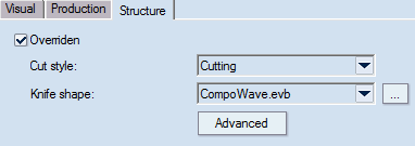
| Overridden |
Select the check box to set a style structure different from
that of the parent one. |
| Cut style |
In the dropdown list, select the style to apply to the knife
shape structure. NOTE: This is the style that will appear in CAM
and 3D drawings.
IMPORTANT: If you have opted for viewing
composite styles, EngView applies
the visual
properties set for the style in Cut style. |
| Knife shape |
In the dropdown list, select the shape for the composite style.
TIP: To view the shape, click Advanced and
inspect the table that appears. You can modify the properties
of the shape (length, shape or angle).
NOTE: You can design knife shapes different from
the ones available in the dropdown list. To do so, use the program's
technology
for designing parametric components. Then load the new components
into the EngView installation.
By default, these components reside in \\EngViewWork7\Settings\TEMPLATES\CompositeStyles
. |
| Advanced |
Opens a dialog box in which you can view the component that
defines the shape. You can edit the component using its parameters. |
- In the tabs, edit the settings as you want them to be.
- To complete the definition of styles, click OK.
Notes
- In the Global Styles dialog box, the Overridden
check boxes are selected by default; they are unavailable for system
styles that have no parent styles. An exception is a system style
created from another system style — for example, the Stripping style
has the Cutting style as parent.
- Since some of the system styles have additional
properties — for example, CutCrease and Perforating and all custom
styles based on them — the edit boxes displayed in the Global Styles
dialog box may vary. In all cases, only the properties which are relevant
to the selected style are displayed.
- You can drag styles up and down the list to
position them where you need them to be.