Every geometric object has a style which is global for the system and determines object properties, such as color, width and pattern of its constructional line or curve. Changing the style globally affects the respective properties of all objects for which it applies. However, you can set the style-conditioned properties of each object individually — for example, you can have two lines in the same style but appearing with different colors, line patterns, and so on, which override the default style settings.
IMPORTANT: The Object Properties dialog box serves various objects in different contexts. These tabs are object-specific and appear dynamically, depending on the object from which you open the dialog box.
To edit object properties
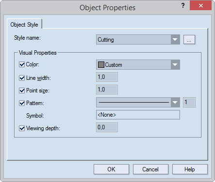
The Object Properties dialog box appears.
Style name | In the list, click to apply a style to the object. This list offers all available styles. To add more styles, click the browse button, and then select the style that you need. |
---|---|
Visual Properties | The properties below define how objects in the style selected in Style name will look on the screen. |
Line width | Sets how wide (in pixels) a line or curve will appear. The
value applies to objects in 1up, layout, print, CAM and 3D drawings;
it does not affect line width in printing jobs and in the generation
of tool path for CAM jobs.
NOTE FOR COMPOSITE STYLES: EngView uses the line width set here also for composite styles, if you have opted not to view the actual pattern of composite styles. |
Point size | Points only. Sets how large points drawn in the selected style will appear. Value range: 0.10 – 15.00. |
Pattern | Sets the pattern in which objects in the style will appear
in 1up, layout, print, CAM and 3D drawings. The dropdown list
contains predefined patterns and an option (Custom...)
for creating custom patterns.
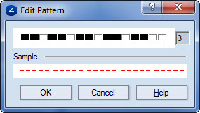
The second box sets the line width, in points, in printing jobs and for the generation of tool path for CAM jobs (see the following note). NOTE FOR USE IN CAM: The value is important for toolpath generation: If the width of the respective CAM tool is narrower than the line width specified here, a different tool path may be generated, involving, for instance, the offsetting of wide lines for the cutting tool (for changes of the line width settings of a style associated with the cutting tool). CUSTOM PATTERN: You can create a custom pattern: Scroll to the bottom of the list, and then click Custom. Then, in the dialog box that appears, clear some black rectangles to create the pattern that you need, and then also set the line width (optional). |
Symbol | Read-only. The mark set to indicate the style when it is listed in a legend. |
Viewing depth | Sets the stack order of a style. If multiple objects in different
styles overlap, the object in the style with the greatest stack
order is visible on the screen. The others are not visible regardless
of when each object was drawn. Value range: –1.00 to 1.00.
EXAMPLE STYLES: If the Cutting style has a stack order of 0.5 and the Axis style has a stack order of –0.4, when objects in the two styles overlap, the one in the Cutting style will always be visible and the one in the Axis style will never be visible. EXAMPLE SELECTIONS: The functionality applies also to selections. For overlapping objects, the object in a style with a greater stack order is always visible even if the object in a style with a lower stack order is selected. If objects in styles with the same stack order overlap, you see the one that is selected. |
Notes