 .
.You can add additional layout 1ups to an already created layout. Before you can add additional layout 1ups, you need to have their drawings in the project.
To place multiple parts in a layout drawing
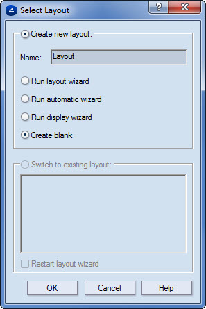
.The Select Layout dialog box appears.
 .
.The Object Properties dialog box appears.
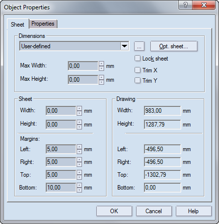
Dimensions Settings for the sheet's size
The dropdown list A list of the sheets that you can use for the layout. To apply a sheet, in the dropdown list, and then select the sheet that you need. If a specific sheet is selected in the dropdown box and its values are then changed, the selected sheet changes too and User-defined appears. To add a predefined sheet that's currently not on the list, click the browse button  , and then, from the dialog box that appears, select the sheet that you need.
Max Width Sets the maximal horizontal length of the sheet. If a specific sheet is selected in the dropdown list, its width and height values appear in Max Width and Max Length. Changes can be made to the width (in the Sheet area), but it cannot exceed the value set in Max Width.
Max Height Sets the maximal vertical length of the sheet. If a specific sheet is selected in the dropdown list, its width and height values appear in Max Width and Max Length. Changes can be made to the length (in the Sheet area), but it cannot exceed the value set in Max Length.
Opt Sheet Opens a dialog from which you can select a sheet that is calculated as the optimal for the active drawing.
Lock sheet Fixes the size of the sheet and disallows its editing.
Trim X Trims the horizontal excess areas between the endmost edges of the active drawing and the sheet.
Trim Y Trims the vertical excess areas between the endmost edges of the active drawing and the sheet.
Sheet Settings for the sheet's size
Width Sets the sheet's horizontal length. Changes made here override the default width value of a selected sheet.
Height Sets the sheet's vertical length. Changes made here override the default length value of a selected sheet.
Margins Settings for the distances — top, left, bottom and right — between the endmost edges of the active drawing and the sheet.
Drawing (Read-only) Information about the rectangular area that encompasses the array of layout 1ups.
Width The distance between the drawing's endmost horizontal edges.
Height The distance between the drawing's endmost vertical edges.
Margins Information about the area's margins — top, left, bottom and right. Negative values mean that the drawing cannot fit into the selected sheet.
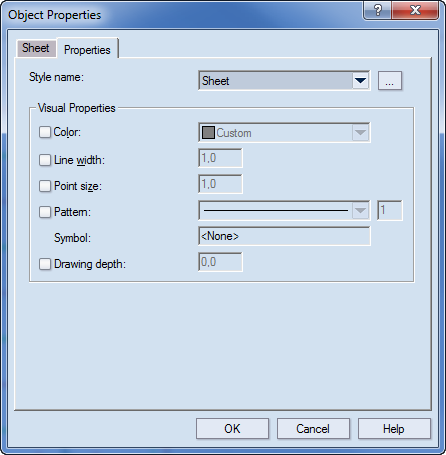
Style name Sets the name of the style assigned to the object. This list offers all styles, including the user-created ones.
Visual Properties
Color Sets the color of the object. By default the color of the assigned style is set.
Line width Sets the width of the constructional line/curve of the object. By default the globally set line width for the object style is set.
The first edit box displays the line width measured in units from 1 to 10. The value applies only to the way the lines of the style will be displayed on the screen in the 1up, layout, print, CAM and 3D Presenter drawings; it does not affect the line width in printing and tool path generation in CAM samplemaking.
In the second edit box, the line width is defined, measured in points. Changes are not visible on the screen; however, the value defines the line width of all objects of the selected style in printing and for tool path generation in CAM samplemaking. It is critical for CAM samplemaking: if the width of the respective CAM tool is smaller than the line width specified here, a different tool path may be generated, involving, for instance, offsetting of wide lines for the cutting tool (for changes of the line width settings of a style associated with the cutting tool).
Point size Sets the point size of the object. By default the globally set point size is assigned for the object style. Value range: [0.10, 15.00]. NOTE: Changes of this property are only applicable to discrete points.
Pattern Sets the pattern of the constructional line or curve of the object. By default the globally set line pattern is assigned for the object style.
The drop-down list contains predefined patterns and an option (Custom...) for creating custom patterns.
The digit-entry field sets the proportional scaling of the length of the pattern segments and the blank intervals between them. Greater values result in longer segments and intervals. Value range: [1, 10].
Symbol
Drawing depth Sets the level of visibility of the object in the drawing area. When objects overlap, the object that you can see in the drawing is the one whose style has the highest drawing depth.
Use in BCT (Board Compression Test)
NOTE: If you leave the sheet unlocked, each time you insert a layout 1up into it, the sheet will become centered around the available layout 1ups.
 .
.The Place Multiple Parts dialog box appears.
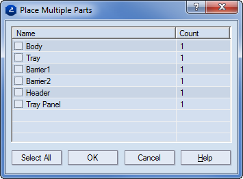
NOTE: In each instance of inserting multiple parts, the selected parts are inserted in a single row, first starting from the origin of the coordinate system. Each repetition of Step 8 will result in placing the parts in a row above the last one.