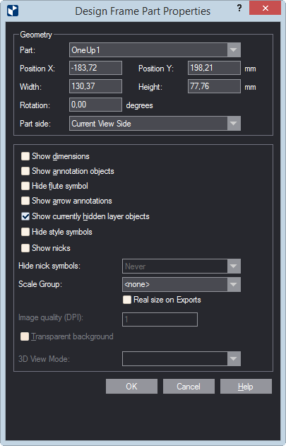
| Print part settings |
|
| Show dimensions |
Makes visible, in the printed document, the dimensions set
in the drawing. |
| The following settings apply to print parts holding
drawings other than 3D. |
| Show annotation objects |
Makes visible, in the printed document, any notes added to
the respective drawing and assigned to the Annotations layer.
IMPORTANT: Select this check box if you want
to see arrow annotations (see below). |
| Hide flute symbol |
Does not display, in the printed document, the symbol that
indicates the direction of the flute or grain.
Show arrow annotations Displays the arrow
annotations.
IMPORTANT: The Show annotation objects
check box (see above) must also be selected. |
| Show currently hidden layer objects |
Makes visible, in the printed document, layer objects that
have been added to the 1up but were made invisible — for example,
to unclutter the view. |
| Hide style symbols |
The print drawing will not display style symbols (if any have
been added to the underlying drawing). |
| Show nicks |
Displays the nicks, if any have been placed
into the 1up. |
| Hide nick symbols |
Settings for whether nick
symbols will be displayed in the print drawing. The options
are:
- Always (nick symbols are never displayed)
- Never (nick symbols are always displayed)
- If all nicks share a width
Consider two cases:
- If the nicks in the drawing are of the same width, the
symbols will not be displayed.
- If the nicks are of different widths, the program displays
only the symbols of the nicks whose number is fewer than 75%
of the total number of nicks. In other words, if there are
same-width nicks whose number is equal to or greater than
75%, their symbols will not be displayed.
|
| Scale Group |
If you want the print parts in your print drawing scaled to
a set ratio, apply a scaling approach here. Make sure that in
the the Name Mapping area you select the print part that
you want scaled. Make sure also that you apply scaling for each
print part that you want scaled. Learn more about scaling
and how to apply it. |
| PDF export in real size |
Select this check box to export the print drawing in its actual
size as a PDF file. "In actual size" means that the
exported drawing will not be scaled down to fit a predefined media
size such as A3, A4 or other. In other words, if your drawing's
size is for example, 1500 mm x 2000 mm, the exported PDF drawing
will keep these measurements, without scaling them down.
TIP: The functionality is linked to the use of the
Scale Group functionality. If you choose not to use a scale group,
only the uppermost drawing in the Name Mapping list will
be exported in actual size, regardless of whether you set the
real-size export also to the rest of the drawings. To export all
the drawings in the project in their actual sizes, add them to
a scale group. To learn how, see the Scale Group guidance
above.
IMPORTANT: The PDF file format has a standard
limitation of 200 inches x 200 inches (appr. 5 meters x 5 meters)
for displaying a document. If the actual measurements of the exported
drawing are larger than these values, the PDF document will cut
the exported drawing to meet this limitation. |
| Show dimensions |
Makes visible, in the printed document, the dimensions set
in the 3D model. |
| |
| The following settings apply to print parts holding
3D drawings. |
| Image quality (DPI) |
(Available when the 3D drawing is selected in the table) Sets
the graphic quality of the 3D image. |
| Transparent background |
Makes transparent the background of the 3D area. This allows
the 3D area to appear in the color set as background for the graphical
area. The functionality is especially useful for white-colored
3D models: Changing the color of the drawing area background makes
white-colored 3D models stand out against it. |
| 3D View Mode |
Sets how the 3D model will be displayed in the print drawing.
The options are: Solid (untransparent panels), Transparent (see-through
panels), Wireframe (grey outlines) and Solid B&W (white untransparent
panels and black edges). |
 .
.