Creating layout from multipart structures on a sheet material
You can produce a series of the same multipart structures — for
examples, a display or a piece of furniture — directly after you have
decided on its structure and design in 3D. You need only create layouts
of its components, send them to a production machine (a cutter, a
digital machine), and then assemble the cut components into actual
structures.
The nesting job procedure that follows takes you through the steps
of how to can create a layout by nesting
the parts of a structure on a sheet material. The example model
is ICB10001 Multiple-Shelf Display. The procedure starts from the
structure's assembled-state drawing.
The nesting job
- In the 3D model view, go to the assembled-state drawing.
- On the 3D tab toolbar, click Create Layout From 3D
 .
.
The Multi-Part Nesting Wizard opens at the
Parameters step. Scroll past the picture to learn how to read it.
| The progress bar |
The progress bar follows the sequence of steps that makes up
the nesting job. The first and last steps — Parameters and Results
— are permanent, while the number of the intermediate steps depends
on (1) the number of the materials used in the 3D model and (2)
the grouping of the parts for the actual nesting (see below).
The name of an intermediate step is a compound generated automatically
from the name of the used material and that of the nesting group.
In the example above, ICB Board White 16, Nesting Group 1. Scroll
below in the table to learn how to use nesting groups. |
| |
| Quantity of displays to produce |
Type how many finished products you want produced as a result
of the nesting job. |
| |
| 1up Nesting Groups |
Here you tell EngView
how to nest the parts on the sheet. When you select a part, it
appears in the preview area on the right. If you have defined
nesting groups in the materials
store, based on a particular material, these are loaded automatically.
IMPORTANT: If you make changes to the nesting
groups that you want to use in the future, you can update them
in the materials
store. Updating the store is automatic for rolled materials,
but not for sheet materials. So do it manually.
Learn how to define a nesting group. |
| Cost Parameters |
Opens a dialog box in which
you tell EngView how to calculate an estimate for the cost of
the production. This estimates does not offer an actual production
cost but is a instrument for ranking layout variants by lowest
cost. |
| Name |
The column displays three nesting job components:
- The name of the used material. Material names are added
automatically by EngView.
This name takes part in the EngView-generated
name of the nesting job's intermediate steps. You cannot edit
the name here.
- The nesting groups defined for the job. Each material used
in the 3D model defines its own set of nesting groups. There
is always a default group, Nesting Group 1, whose name you
can neither modify nor delete. You can tell EngView to always
nest certain parts together. In this case, you need to group
the parts into a separate group. To create a group:
- Select the name of the material.
- Click the Plus button above.
- In the row that appears, edit the group's name as you
need it.
- From Nesting Group 1, drag into the new group the parts
that you want to group individually into the new group.
- Repeat Steps 1–4 for each new group you choose to create.
- The indvidual parts that will take part in the nesting
job. By default, when you begin, you see all available parts
in Nesting Group 1. If you choose to have some parts always
processed together, create nesting groups for them. If you
do not want to use a part in the nesting job, leave its check
box empty. Article indicates the name of the article
applied onto the part.
|
| Rotation |
Type an angle that EngView
will use to rotate the part while populating the sheet. To specify
a value for all the parts, set it across the name of the nesting
group. To set an individual angle value for a part, type it across
the part's name. |
| Spacing |
Type a gap between the parts. To specify a global value, type
it across the name of the nesting group. To set an individual
spacing for a part, type it across its name. |
| Delivery Quantity |
Specify how many pieces of this part you want produced. |
| Overproduction |
Specify as percentage the amount of production that the customer
is willing to pay for in excess of the combined total as
calculated from Quantity + Allowance. |
| Allowance |
Set spoilage for the current part. Spoilage is the number of
excess pieces that will be produced for the purpose of setting
up the die. Generally, after setting up the die, these pieces
are recycled. |
| |
| Sheets |
The sheets that will be used in the nesting job. Each material
used in the 3D model defines its own set of sheets. NOTE: To add
a sheet, click any row in the table, and then click the Plus button;
then, from the list that appears, select a sheet. To delete a
sheet, click it, and then click the Remove button. |
| The Sheets List |
A list of the sheets selected for production. For each material,
you see two default sheets groups: All Sheets and Nesting Group
1. For each new nesting group you choose to create, a new sheets
group appears here. If you are working with multiple nesting groups,
here you can add sheets to each one of them. To add a sheet:
- Select a group's name.
- Click the Plus button.
- From the list that appears, select the sheet that you
want to work with.
- Repeat Steps 1–3 for each sheet you want to add. Notice
that each sheet you add automatically goes into both its
own nesting group and the All Sheets group.
NOTE: In a nesting group, you can add multiple sheets but use
only some of them. To choose which ones to use, use the mouse
to select or deselect the check box in front of each sheet. Alternatively,
use the Space bar to select or deselect sheets and nesting groups. |
| Flute/Grain direction |
Sets whether the sheet will take into account the grain or
flute of the material. The options are:
- fdX. Arranges the parts according to the horizontal
flute/grain.
- fdY. Arranges the parts according to the horizontal
flute/grain.
- fdAny. Ignores the direction of the flute/grain.
|
| Count |
Sets the number of sheets available, the default value is Infinite.
You can set your own number. In that case, if EngView
computes a number that is greater than the one set here, a red
notification and a tooltip alert will appear in the Total Sheet
Count column in the Results step. |
| Width |
The horizontal length of
the sheet. |
| Height |
The vertical length of the
sheet. |
| Left, Right, Top, Bottom |
The values for the sheet's left, right, upper and lower margins |
| |
| The Preview Pane |
A preview of the part selected in the Name column |
 Single Object Dimension Single Object Dimension |
Click to measure the lengths
of individual objects in the preview area. |
 Associative (Two Object) Dimension Associative (Two Object) Dimension |
Click to measure distances
between two objects. |
 Show Images Show Images |
If images have been applied to the parts, clicking this button
hides/displays them. |
 Clipped Image Clipped Image |
If images have been applied onto the parts that go outside
the parts, clicking this button clips the images to make them
fit the parts' actual areas. |
 View Bleed View Bleed |
Hides/Displays the bleed in the preview area. |
- Click the Cost Parameters icon
 and in it
set how you want EngView
to compute the cost estimate. See details
about how to do this.
and in it
set how you want EngView
to compute the cost estimate. See details
about how to do this.
- Edit the sheet and grouping settings to make them work for
your case. Then click Next to continue.
An intermediate step appears. A general info
about the intermediate steps follows:
The number of intermediate steps is determined by (1) the number
of used materials and (2) the number of nesting groups (see the note
for progress bar in the previous step). The name of an intermediate
step is a compound from the name of the used material and that of
the nesting group. This means that if you work with multiple materials,
you will have as many individual pages as materials, and if you work
with multiple nesting groups, you will have as many pages as groups.
In other words, if you work with:
- One material and one nesting group, the wizard will display
one intermediate step.
- Two materials and two nesting groups, the wizard will display
four intermediate steps.
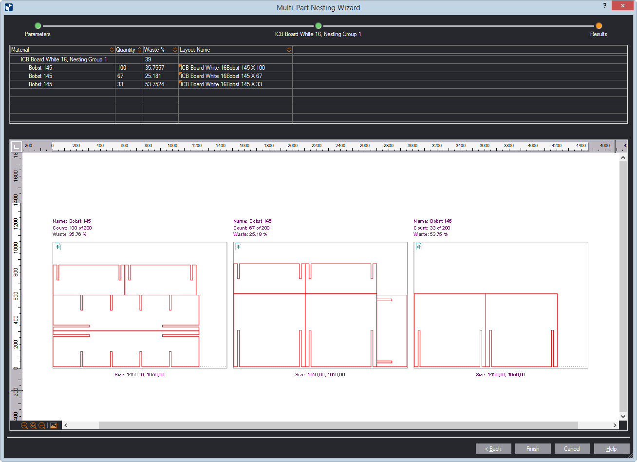
Scroll past the picture that follows to learn how to read an intermediate
step.
| The Left-Hand Pane |
The pane lists the layout variants that EngView
has computed from the parameters you have supplied. The variants
are listed in descending order, ranked by the lowest cost and
waste. |
| Layout Variants |
The names of the sheets that EngView
will use for the nesting job. |
| Layout Variants |
How many dies (or sheets) the job requires. |
| Total Sheet Count |
The total number of sheets EngView
has computed for the nesting job. Note that if you see a red text
and an alert tooltip here, this means that in Count (in
the Parameters step) you have entered a number that is smaller
than the one EngView
has computed. This alert will not stop the nesting job, but it
is best to go back to the Parameters step and modify the value
in Count. |
| Waste % |
The overall waste in relation to the total area of the sheet |
| Model Cost Estimate |
The relative cost for the variant |
| |
| |
| The Middle Pane |
The pane lists a breakdown of the parts combinations by particular
sheet. For each part are displayed its production volume (in Delivery
Qnty, Produced and Excess), spatial positioning on the sheet (Rotation),
and per-sheet distribution. |
| The Right-Hand Pane |
The pane lists the 1ups (parts) featured in the variant selected
in the left-hand pane. For each part are displayed its production
volume (in Delivery Qnty, Produced and Excess), spatial positioning
on the sheet (Rotation), and per-sheet distribution. |
| 1up |
The name of the 1up (part). When you select a part, it is highlighted
in the preview pane in all the sheets it appears. |
| Rotation |
The angle of rotation for the part when arrayed in the sheet |
| Delivery Quantity |
How many pieces of this part you want produced. If colored
results appear, see what they mean*. |
| Produced |
The number of parts the nesting job will actually produce.
If colored results appear, see what they mean*. |
| Excess |
The difference between the values in Produced and in
Delivery Quantity. If colored results appear, see what
they mean*. |
| Per Sheet |
Indicates how many pieces of the part there are in each sheet
in which the part appears. Examples:
- sh1:1 means Sheet 1 contains one pieces of the part.
- sh2:3 means Sheet 2 contains three pieces.
- sh2:2, sh3:6 means Sheet 2 contains two pieces and Sheet
3 contains six pieces.
When you select the row, EngView
highlights the part in the preview pane in all the sheets it appears.
If colored results appear, see what they mean*. |
| |
| *Colored results |
Depending on the amounts you have set for a nesting job, in
the right-hand pane you may see colored results in the columns
Delivery Quantity, Produced, Excess and Per Sheet. The colors
means as follows:
- Blue. The amounts
produced are greater than what you have set. That means you
will have surplus output.
- Red. The amounts produced
are smaller than what you have set. This means you will have
smaller output than what you need.
|
| |
| The Preview Pane |
A preview of the layouts EngView
has computed under the selected variant. If a row is selected
in the right-hand pane, the respective part is highlighted in
all the sheets in which it appears. |
| Single Object Dimension |
Click to measure the lengths
of individual objects in the preview area. |
| Associative (Two Object) Dimension |
Click to measure distances
between two objects. |
| Show Images |
If images have been applied to the parts, clicking this button
hides/displays them. |
| Clipped Image |
If images have been applied onto the parts that go outside
the parts, clicking this button clips the images to make them
fit the parts' actual areas. |
| View Bleed |
Hides/Displays the bleed in the preview area. |