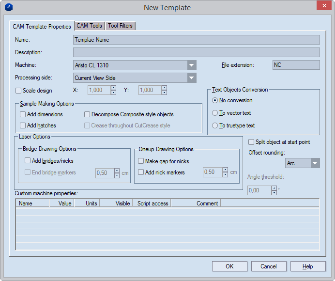
| Name |
The name of a new or the currently selected template. |
| Description |
Notes about the template. |
| Machine |
Assigns a CAM machine to the template. The list displays only
the CAM machines for which the 'Enabled' property is selected
in the CAM Machines tab in the CAM
Options dialog box. CAM tools inherit the custom properties
set for the CAM machine used in the CAM template. |
| Processing side |
Sets the default side for processing of CAM jobs.
NOTE: If changes have been made to the CAM drawing,
an indication appears at the side of the dropdown list indicating
these changes. "Current View Side" is the default setting.
TIP: You can change the view side of CAM drawing
by using the Front/Rear Side Marker icon (in the graphical
area) or by changing the alignment settings in the Coordinate System Alignment
dialog box. Both depend on what is set in Processing side. |
| File extension |
Set the extension for the NC file created during the NC generation
process. |
| Scale design |
Scales the design that will be processed on a rotary die: X
(horizontal scale); (Y) vertical scale. |
| |
| Sample Making Options |
Settings that the current CAM template uses to generate tool
paths. |
| Add dimensions |
Includes for processing the existing dimension lines in the
CAM drawing so that the CAM plotter can print them onto the sample.
The CAM drawing is updated automatically. The dimension lines
will be added as objects in the Dimensions style. In most cases,
the tool filters available in your CAM template will not cover
these new objects and no associations will be created for them.
To resolve this, create a new tool
filter to associate them with the respective tool (for example,
Drawing Pen), and then generate
the tool path again. |
| Add hatches |
Treats hatches as separate objects. This is useful if you want
to strengthen areas that need to be glued — for example, glue
flaps. At these particular areas, the cutting head turns every
hatch into a slit, which makes the surface rougher and adds solidity
to the glued area. |
| Decompose Composite Style objects |
Turns objects in composite styles into discrete objects, which
are then processed by the plotter. |
| Create throughout CutCrease style |
For objects in CutCrease style, makes the creasing tool run
throughout the contour. This is then followed by the cutting tool,
which processes only the areas to be cut. |
| |
| Laser Options |
The two groups that follow control the management of bridges
and nicks |
| Bridge Drawing Options |
Settings that control the placement of bridges and bridge markers |
| Add bridges |
Substitutes the gaps (bridges) with objects. By applying a
tool
filter, the laser machine can process these objects in a specific
way. |
| End bridge markers |
Places perpendicular markers at the end of bridges to serve
as highlights. In the value box, type a value for the marker length.
Markers carry the Marker style. |
| |
| OneUp Drawing Options |
Settings for the placement of gaps and nick markers in 1ups |
| Make gap for nicks |
Places a gap where a nick is drawn. The gap's width is identical
with that of the nick. |
| Add nick markers |
Places a marker for a drawn nick. In the value box, type a
value for the marker length. The marker's style is identical with
that of the nick.
NOTE: To process this marker, create a tool filter. |
| |
| Text Object Conversion |
Settings that control how text is converted into vector and
TrueType fonts. |
| No conversion |
The text object is without conversion. If the text is TrueType,
it cannot be cut or creased. |
| To vector text |
Converts the text into a vector one.
IMPORTANT: CAM samplemaking and diemaking
jobs process only vector texts. |
| To TrueType text |
Converts text objects (normal text) to TrueType. |
| Split objects at start point |
Makes the cutting job start at the point where the tool head
is positioned.
NOTE: In CAM jobs, creasing jobs precede cutting
ones. |
| Offset rounding |
Sets a shape for the offset rounding — an arc, a corner or
a sharp cut.
NOTE: If you choose different types of rounding,
create a new tool path after each new selection. |
| |

Rounding with an arc

Rounding with a corner

Rounding with a sharp cut
|
| Angle threshold |
Available when "Corner" is selected in Offset
rounding. Sets the largest angle that the offset's corner
rounding can take. |
| |
| Custom Machine Properties |
The properties in this area were created along
with the properties of the machine. Here you can only edit
their values as you need them for the job in hand. |
| Name |
The name of the property. |
| Value |
Sets the default value for the property. |
| Units |
Sets the default measurement units. |
| Visible |
Opens a dialog box in which a new template is defined. |
| Script access |
Tells you how the script handles the tool's value setting.
The options are:
- Read-only. The script uses the value of the property
as it is defined by the CAM template, making no changes to
it during the job.
- Local Only. During the job the script dynamically
makes changes to the value of the property. When the job is
completed, these changes are lost.
- Committable. During the job the script dynamically
makes changes to the property value. When the job is completed,
the changes are saved to the CAM template and are applied
when the next job is started.
|
| Comment |
Type notes about the property. |


