The profiles are constructed in EngView Synergy and are used in EngView for creating composite styles. The profiles (shapes) of composite styles are built from one or more segments. Descriptions of these segments follows:
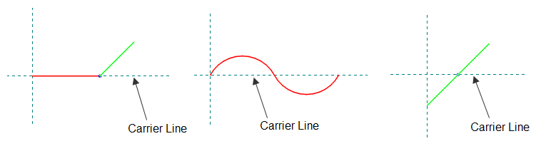
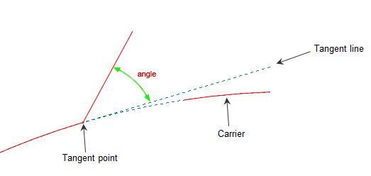
The carrier is the axis around which the profile is constructed. The carrier takes the shape of the object on which the composite style is applied. For example, if the object is an arc, the carrier will bend along the shape of the arc.
IMPORTANT: When you are drawing a segment for a composite style profile, the drawing must begin on the y-axis. The x-axis is the carrier.
Composite style profiles as constructed in EngView Synergy.
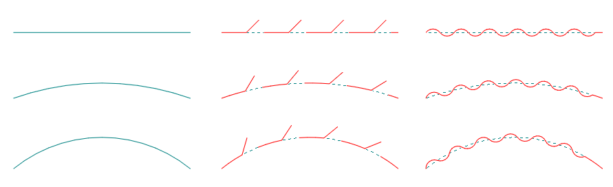
To the left are the profiles (shapes) of the object on which a composite style has been applied (View Composites is not turned on). In the middle and to the right the actual structure of the composite styles are shown (View Composites is turned on) and how they bend along the carrier.
A profile (shape) can have two types of segments: (1) segments that take on the shape of the object on which the composite style is applied (bendable) and (2) segments that remain straight regardless of the shape of the object on which the style is applied:
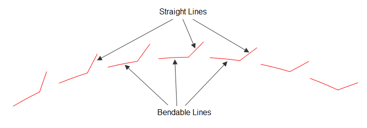
The bendable segments adopt the shape of the object on which the style is applied. The straight one remains as they were drawn regardless of the shape of the object.
These segments follow the shape of the object on which they are applied. IMPORTANT: The bendable segments must be drawn in the Plotting style and in red. Learn how to apply a color to a style.
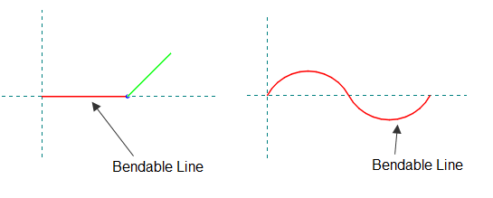
These segments do not follow the shape of the object on which they are applied. IMPORTANT: The straight segments must be drawn in the Plotting style and in green. Learn how to apply a color to a style.
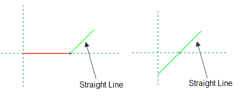
The green segment remains straight after the carrier is bent along the shape of the object.
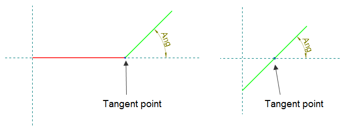
The point through which the tangent line is drawn that defines the angle at which a green segment (straight) intersects the carrier. IMPORTANT: The tangent point must be drawn in the Plotting style and in the color Blue. Learn how to apply a color to a style.
The profiles for the styles Zipper (left) and HandHole (right) as constructed in EngView Synergy
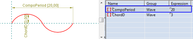
The horizontal distance between the two leftmost points at which the composite profile is repeated along the carrier. In the tablular area, the period is indicated by the parameter CompoPeriod.
On the left, an object on which the Zipper style has been applied. On the right, the style's profile (shape) as it was created in EngView Synergy.
On the left, an object on which the Wave style has been applied. On the right, the style's profile (shape) as it was created in EngView Synergy.