Designing perfa fonts
- On the Tools menu, point to EngView Font, and
then click New Perfa Font.
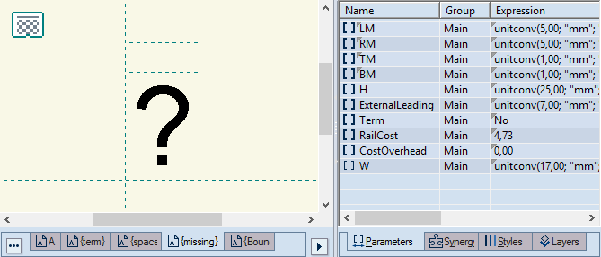
A perfa font project opens with five default
drawings — A; {term}*; {space}*; {missing}* and {BoundingRect}* —
and accompanying parameters*.
WARNING: Do not rename these drawings and parameters.
Drawing the PERFA symbols
IMPORTANT: In the perfa font project, draw each
symbol in an individual drawing. This means that a perfa font will
have as many drawings as is the number of its symbols. The first symbol
drawing (A) is loaded by default. If you are creating a symbol other
than CAPITAL A, rename the drawing by double-clicking it.
- In the tabular area, in the Expression cell assign a
value to the parameter H. This global parameter controls the height
of the symbol plates.
NOTE ON UNIT CONVERSION: A parameter's expression
uses a three-argument function: unitconv(Arg
1; "Arg 2";
"current"), Arg
1 is a value; Arg 2 sets the measurements units for the Arg 1
value when it was set; Arg 3=current guarantees that when you
apply the font to a structure, the Arg 1 value will be converted
in currently used metric
units. See the following example:
unitconv(25,00;
"mm"; "current"). Here, the program
treats the parameter's value
(25) in the metric units set in
the second argument (mm). When we leave the third argument
"current," when we apply the font to a structure in
a project whose metric units are millimeters, the font height
will stay 25 mm high and will be presented in millimeters. If,
on the other hand, we apply the font to a structure in a project
whose metric units are inches, the font height will stay the same
but presented as 13/64 inches (25 mm).
- Assign a value to the parameter W. This local parameter controls
the width of the symbol's plate and plays a role in the calculation
of the perfa text's overall length.
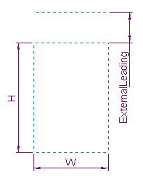
- Assign a value to the parameter ExternalLeading. This global
parameter controls the vertical distance (spacing) between symbols'
cells in multi-line texts (pictured).

Now begin drawing the symbol's circles, creating
the shape of the symbol as you want it to be.
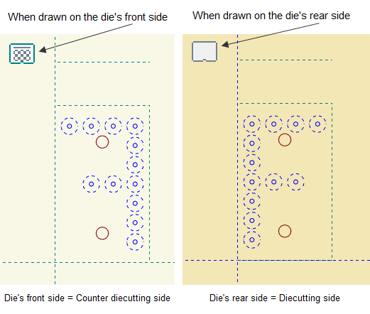
IMPORTANT: Pay attention to the side of the drawing
on which you are creating the symbol — the dieboard's front or rear
side. See the image below for guidance of how drawing sides affect
symbols' orientations.
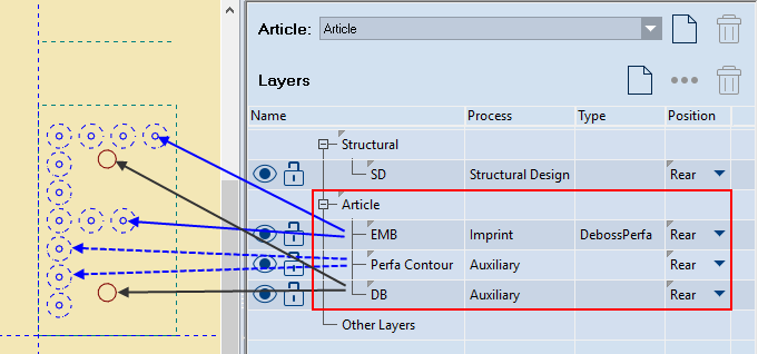
- Draw the inner circles
in the perfa style. Each circle represents one pin. Then (1) in
the tabular area go to the Layers & Objects tab and
create a DebossPerfa layer
(an imprint layer), (2) in Position, select Rear,
and then (3) assign
the circles to the DebossPerfa layer.
- (Optional) Draw all outer circles in the Perfa Contour style.
In the 1up drawing, they make the symbol readable when you zoom
out. Then (1) in the tabular area, go to the Layers & Objects
tab and create an Auxiliary
layer with the name Perfa Contour, (2) in Position,
select Rear, and then (3) assign
the circles to this layer.
- (Optional) Draw fastening holes in the Dieboard style. These
represent the holes for any fasteners that will hold the symbol's
plate to the die. Then (1) in the tabular area, go to the layers
& Objects tab, and create an Auxiliary layer with the name
DB. Assign the holes to this layer.
IMPORTANT: The layers created in Steps 5–7 must
be assigned to the group Article (pictured).
- Assign a value to the parameter
Cost. This is the price of the current symbol. It will be used
in the calculation of
the perfa text.
- Name the symbol's drawing.
IMPORTANT: The name must be identical with that
of the symbol drawn in it. For example, a drawing of the symbol for
the capital letter F must be named a capital letter F.
Drawing the fastening symbols (used for MINI perfa fonts)
Fastener plates represent holes through which bolts or other fasteners
will pass to hold the perfa text to the dieboard. These holes are
used mainly in MINI perfa fonts, which use smaller-sized plates.
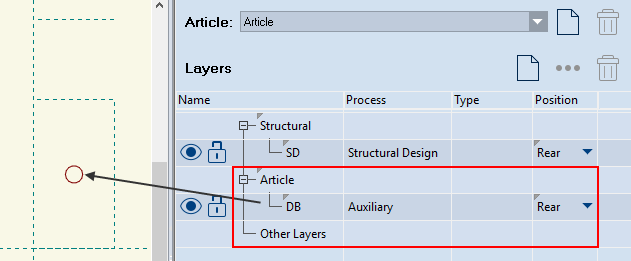
- Open the {term} drawing, and begin drawing the fastener circles.
Use the Dieboard style. Then (1) in the tabular area, go to the
Layers & Objects tab and create
an Auxiliary layer with the name DB, (2) Assign
the circles to this layer.
IMPORTANT: The layer must be assigned to a group
Article (pictured).
- Assign a value to the parameter W. This local parameter controls
the width of the plate and plays a role in the calculation of
the perfa text's total length.
- Assign a value to the parameter Cost. It controls the price
of the plate. It will be used in the calculation of the perfa
text.
- Assign the value Yes to the parameter Term. This parameter
tells the program that this font will use additional fastening
plates. As a result, this symbol will appear automatically on
both end of the perfa text.
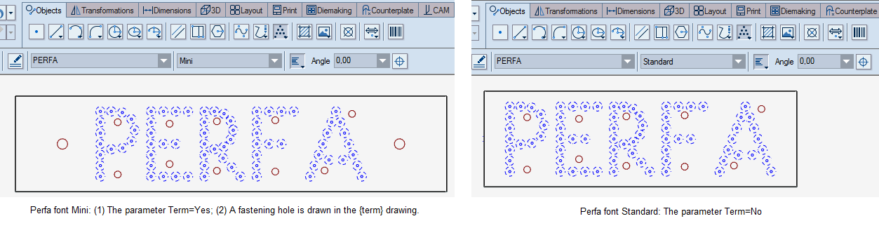
NOTE: If the perfa font does not use fasteners — for
example, a Standard perfa font — there is no need for you to draw
anything in the {term} drawing. In this case, the value of the parameter
Term must be No. See the following picture for how a MINI perfa font
(left) uses fastener plates and how a Standard perfa font (right)
does not.
Drawing the missing symbols
You can draw symbols that will mark any symbols you may type but
the program will not recognize. If you are typing a symbol that the
program does not recognize because the selected font has no such symbol,
the program will use the missing symbol to indicate it.
- In the {missing} drawing, draw the symbol that you want to
mark unrecognized symbols.
- Assign a value for the parameter W.
Drawing the space
- If the perfa font will have a plate for a space — for example,
a blank plate with no pins — in the {space} drawing, assign a
value to the parameter W and leave the drawing empty.
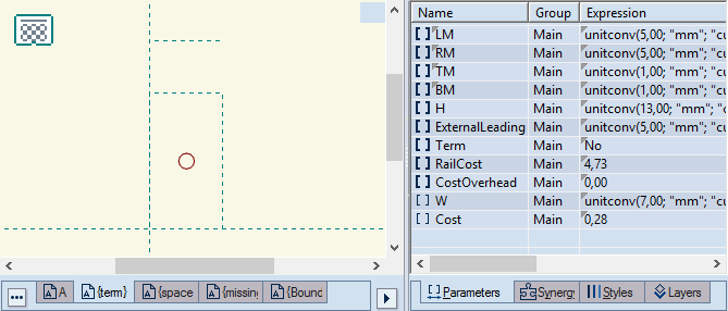
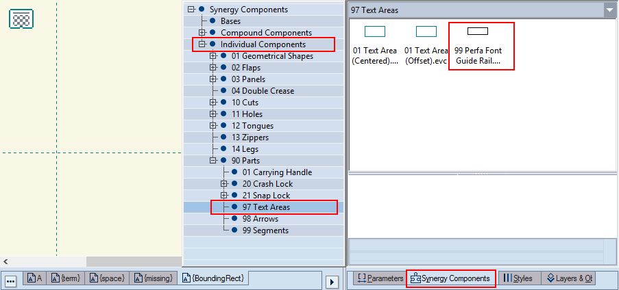
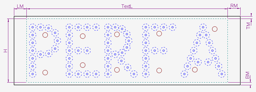
Drawing the bounding rectangle for the guide rail
If, when using the perfa font, you want to visualize the size of
the guide-rail that holds the text, in the {BoundingRect} drawing
drag the base component 99 Perfa Font Guide Rail.evb. It will resize
automatically around the perfa text. Find the component in Individual
Components\90 Parts\97 Text Areas (pictured).
- While you are positioning the component, make sure the control
point (at pointer's end) lies on the origin of the coordinate
system point (Oxy).
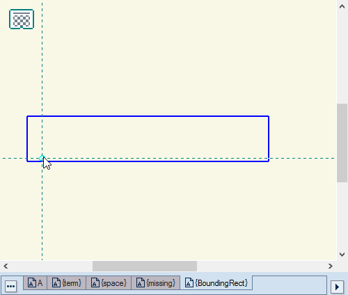
- Click to position the component.
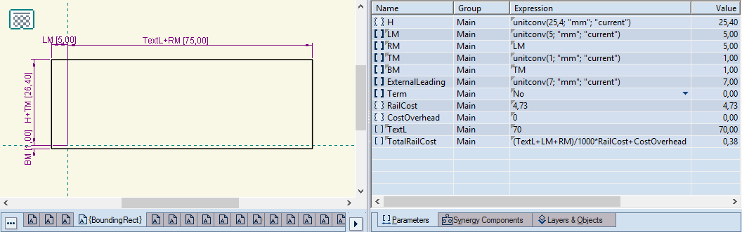
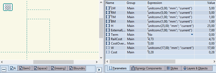
- Assign values to the
margins (LM, RM, TM, BM), which will define the size of the guard-rail.
- Assign a value to the parameter RailCost, which defines the
price of the guide-rail. NOTE: The formula behind the price —
(TextL+LM+RM)/1000*RailCost+CostOverhead) — takes it that RailCost
is a price per linear meter. If you will use a different metric,
edit the formula to suit your case.
- (Optional) Assign a value to the parameter CostOverhead.
The drawing has two local parameters:
TextL EngView fills
the parameter's expression according to the size of the typed text;
it adds each value of the parameter W, assigned to each symbol in
the perfa text.
TotalRailCost
The total cost of the guide-rail. You can edit the parameter formula
as your case requires. The parameter plays a role in the calculation
of the perfa text's price.
Saving the perfa font
After you have defined the perfa font, you proceed by saving it
and making it ready for use. Perfa fonts are saved as EVFNT files
in your installation's Perfa Fonts folder. By default, the path is
C:\EngViewWork7\Settings\EngView Fonts\Perfa Fonts.
- On the File menu, click Save.
The Save As dialog box appears opening
the Perfa Fonts directory.
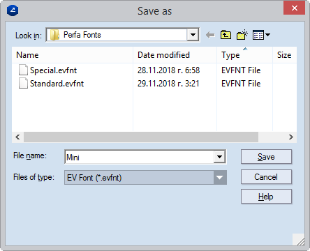
- Give the perfa font file a name that makes sense to you, and
then click Save.
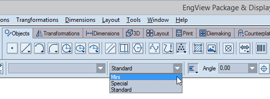
- To begin using the font, restart the program. After you restart,
you will see your new font in the contextual edit bar when you
start typing perfa texts (pictured).