Print drawing with 1up and layout drawings
Print drawing with 1up and a 3D drawing
You can create a print drawing by applying a predefined print template. A template sets the types of project drawings that will be on the print drawing — 1ups, layouts, 3D models, counterplates, bridges drawings, and others — and also sizes their positions. Also pre-defined are project-related data-extracting formulas, statistics about used rules, accompanying text, and other data that you plan to use regularly. This technique is preferable if you want to present your projects in a pre-designed layout and by extracting specific data.
Learn more about how to create print templates.
Print drawing with 1up and layout drawings
Print drawing with 1up and a 3D drawing
To create a print drawing by applying a print template
 .
.The Print Frame Placement dialog box appears. In it, you select the template that you need for print drawing.
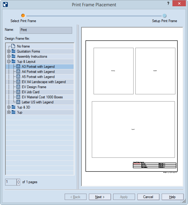
NOTE: The list you see in the dialog box follows the structure of the directory of your installation that contains the design frames — C:\EngViewWork7\Settings\DESIGN FRAMES.
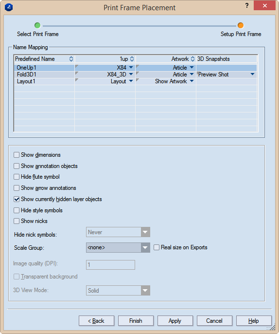
The Print Frame Placement dialog box appears.
| Name Mapping | Name Mapping |
|---|---|
| Predefined name | Lists the predefined design frames in the template. |
| 1up | This is where you map a drawing from your current project to a predefined design frame from the template. To map a drawing, click in the respective field to open the list of drawings, and then select the drawing that you want to place into the design frame. Placing a drawing into a design frame produces a print frame in the final print drawing. |
| Artwork | The article applied to the selected drawing. |
| 3D Snapshots | (Available only if a 3D drawing is selected in the 1up column field.) Lists the names of the available 3D shots. To assign a snapshot, click the respective field to open the list, and then select the one you want. |
| Print part settings | |
| Show dimensions | Makes visible, in the printed document, the dimensions set in the drawing. |
|---|---|
| The following settings apply to print parts holding drawings other than 3D. | |
| Show annotation objects | Makes visible, in the printed document, any notes added to
the respective drawing and assigned to the Annotations layer.
IMPORTANT: Select this check box if you want to see arrow annotations (see below). |
| Hide flute symbol | Does not display, in the printed document, the symbol that
indicates the direction of the flute or grain.
Show arrow annotations Displays the arrow annotations. IMPORTANT: The Show annotation objects check box (see above) must also be selected. |
| Show currently hidden layer objects | Makes visible, in the printed document, layer objects that have been added to the 1up but were made invisible — for example, to unclutter the view. |
| Hide style symbols | The print drawing will not display style symbols (if any have been added to the underlying drawing). |
| Show nicks | Displays the nicks, if any have been placed into the 1up. |
| Hide nick symbols | Settings for whether nick
symbols will be displayed in the print drawing. The options
are:
|
| Scale Group | If you want the print parts in your print drawing scaled to a set ratio, apply a scaling approach here. Make sure that in the the Name Mapping area you select the print part that you want scaled. Make sure also that you apply scaling for each print part that you want scaled. Learn more about scaling and how to apply it. |
| PDF export in real size | Select this check box to export the print drawing in its actual
size as a PDF file. "In actual size" means that the
exported drawing will not be scaled down to fit a predefined media
size such as A3, A4 or other. In other words, if your drawing's
size is for example, 1500 mm x 2000 mm, the exported PDF drawing
will keep these measurements, without scaling them down.
TIP: The functionality is linked to the use of the Scale Group functionality. If you choose not to use a scale group, only the uppermost drawing in the Name Mapping list will be exported in actual size, regardless of whether you set the real-size export also to the rest of the drawings. To export all the drawings in the project in their actual sizes, add them to a scale group. To learn how, see the Scale Group guidance above. IMPORTANT: The PDF file format has a standard limitation of 200 inches x 200 inches (appr. 5 meters x 5 meters) for displaying a document. If the actual measurements of the exported drawing are larger than these values, the PDF document will cut the exported drawing to meet this limitation. |
| Show dimensions | Makes visible, in the printed document, the dimensions set in the 3D model. |
| The following settings apply to print parts holding 3D drawings. | |
| Image quality (DPI) | (Available when the 3D drawing is selected in the table) Sets the graphic quality of the 3D image. |
| Transparent background | Makes transparent the background of the 3D area. This allows the 3D area to appear in the color set as background for the graphical area. The functionality is especially useful for white-colored 3D models: Changing the color of the drawing area background makes white-colored 3D models stand out against it. |
| 3D View Mode | Sets how the 3D model will be displayed in the print drawing. The options are: Solid (untransparent panels), Transparent (see-through panels), Wireframe (grey outlines) and Solid B&W (white untransparent panels and black edges). |
NOTE: If in a print drawing you apply a design frame that has more predefined areas than the number of drawings in the project, some areas in the print drawing will remain empty. For example, if you apply a design frame that has three 1up areas, but your project has only two 1up drawings — one area will remain empty. When you click the frame, warnings appear at the empty areas in the print drawing to indicate a predefined but unused area.
NOTE: By completing the above procedure, you have created a print drawing that displays the types of information set in the applied print template. If you choose to add more data to the print drawing, note that they will not become part of the used template.