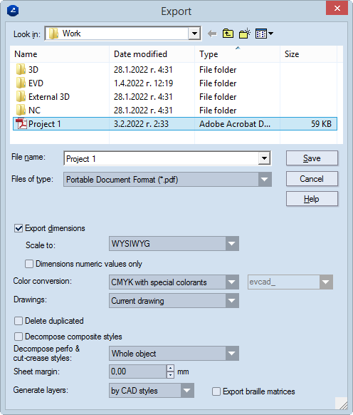
Export dimensions When the check box is selected, you can make custom settings about how dimension lines are exported. Normally how dimension lines are exported is set in the drawing's own properties. If a project contains at least one drawing that has no preset dimensions scaling factor, the Scale To list is available, and you can set scaling for the dimension lines in the entire project.
IMPORTANT: By default, the check box is empty, and dimensions are exported according to their predefined scaling patterns. To use a scaling pattern different from the predefined one, select the check box, and then, in the Scale To dropdown list, select a different pattern or define a new one.
Scale to (Unavailable when a global scaling pattern has been defined or a specific pattern has been defined for the drawing.) Sets a scaling pattern for how dimensions text will be exported. The options are:
Dimensions numeric values only When the check box is selected, only the values of measure lines will be exported buat no letters. If there is at least one drawing without a set scaling factor, Scale to is available, and you can select a scaling option. If the text Applied to nonscaled drawings appears, the scaling will be applied only to the drawings that do not have a predefined scaling factor. This will not override any previously defined values.
Color conversion Sets the color scheme to convert the file's colors during export. Тhe following color conversion options are available: CMYK, RGB, Single spot color, Single spot color (rich view), Multiple spot color and Multiple spot color (rich view*).
* Rich view spot colors enable the export of styles in colors other than the default ones. For example, you can assign the Cutting style to be in a style different from the default one (red). After the file is exported, PDF files visualize the newly assigned, machine-recognized style.
NOTE ON NAMES FOR EXPORTED SPOT COLORS: When spot colors are selected for export, in the box type the name of the exported spot color.
Drawings sets which drawings in a project will be exported. The options:
NOTE: When this option is selected, a note appears opposite the Scale to dropdown list. The note, which reads Applied to non-scaled drawings, indicates that a scaling pattern needs to be set for the drawings in the project for which no scaling pattern has been set. The scaling pattern can be the same as that in the rest of the drawings in the project or different.
Delete duplicated Deletes any overlapping objects in the original EVD file.
IMPORTANT FOR EXPORTING LAYOUT DRAWINGS: When the check box is selected, all layout 1ups (parts) are converted into separate objects. In the exported file, (1) no layer groups are formed for the layout 1ups (parts) and (2) in each case of overlapping objects, the objects are merged into a single object. USAGE NOTE: Using this file conversion functionality comes in especially handy when exporting EngView data to certain programs — for example, Zund Cut Center.
Decompose composite styles After the drawing has been exported, objects in composite styles are broken down to discrete elements. These elements take the properties of the style set in the Structure tab of the original composite style.
IMPORTANT: If the check box is left empty, after export the objects will have the line width set in the Production tab of the original composite style; their color and pattern will be those set in the Visual tab. Learn about the structure of composite styles.
Decompose perforatings After the drawing has been exported, objects in the CutCrease and Perforating styles are broken down to discrete elements according to the chosen criteria. The options:
Sheet margin In the exported drawing, margins are set around the text on all sides.
Generate layers Exports the drawing by layers. In the drop-down list, select an exporting method:
Export braille matrices In exporting braille inscriptions, EngView exports the braille matrix along with the braille text. The matrix is exported in a separate layer or style (for details, see Generate layers above) and in the automatically generated Braille Matrix style.