 .
.To use template layout
.The Select Layout dialog box appears.
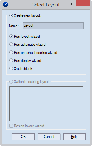
Create new layout (The default choice when there is no layout drawing) Begins the creation of a new layout. To create a layout, inspect the options that follow, and then select the layout-making method that you need.
Name The name of the layout drawing. By default, names are assigned in the following order: Layout, Layout_1, Layout_2,..., Layout_N, where N is the end number of layout drawings. If you want a different name, type it here.
Run layout wizard This layout technique sets rules for the arrangement of four layout parts in two rows and two columns. You then select a rule, and the program follows it to populate a selected sheet with layout parts. Using waste area-based statistics, you can control how the program applies the selected layout template onto different sheet sizes.
You can choose between using a predefined template for arraying a layout, or defining your own template. In the latter case, the program saves the template, and you can then use it for building new layouts in future jobs or use it in other layout techniques – for example, automatic layout or rectangular array.
Run automatic wizard The technique offers detailed statistics for all the combinations of the existing layout templates as applied to various sheet sizes. The combinations are ranked by waste area and contrastingly visualized, which helps you select the solution you need for your production needs.
Run one-sheet nesting The technique nests the layout parts onto a single sheet, taking into account the required production run so that as few sheets are used as possible. You select a sheet and set a production run. The program then produces the optimal distribution of the 1ups for the selected sheet. The Single-Sheet Nesting technique is best suited (1) for laying out the same structure but fitted with different graphics or (2) when you need to lay out 1ups with irregular shapes, where using the template-based or automatic layout technique would produce greater waste.
Run display wizard A functionality best suited for building layouts out of the components of a multipart structure — for example, displays or furniture items for producing a set quantity with least costs. The program separates the structure's parts automatically into groups by material, and then nests them into the set sheet sizes. The layout results are then ranked by cost, not by waste area. This layout technique is best when the production uses samplemaking machines.
Create blank The program opens a blank drawing in which you begin to build you own layout by manually adding the sheet and the layout parts. You can save time by using arraying methods — rectangular array or part connection array.
Switch to existing layout (The default choice when there is a previously designed layout) A list of the available layout drawings are displayed, and you can choose the one that you need, which then opens. The available layout drawing are listed.
Restart layout wizard (Available only when the Switch to existing layout option is selected.) Restarts the layout-making functionality — wizard-guided or manual — that was used to create the current array. If the template-defining layout functionality was used, the automatic layout functionality starts.
The Automatic Layout wizard starts, displaying the Select Template step.
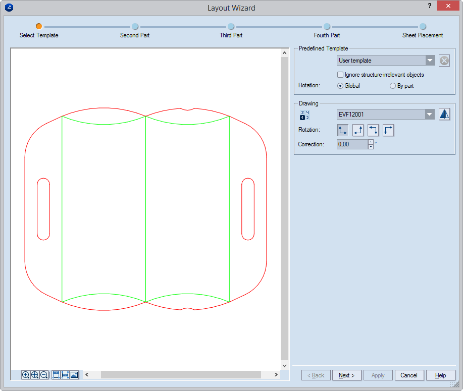
Predefined Template Lists the available options to define a template in the current project. Choosing the User template option lets you define a layout of your own by going through the wizard. In all other cases, a predefined template is loaded and opens the final wizard page, in which you can make final corrections to the layout.
Delete custom template  (available only for custom layout templates) Deletes the selected custom
layout template. The default layout templates — 1x1, 2 rows,
2 columns, 2 parts in rows, and 2 parts in columns
— cannot be deleted; for them the button is unavailable.
(available only for custom layout templates) Deletes the selected custom
layout template. The default layout templates — 1x1, 2 rows,
2 columns, 2 parts in rows, and 2 parts in columns
— cannot be deleted; for them the button is unavailable.
Ignore structure-irrelevant objects When this check box is selected, the layout will not include objects that do not affect the structure. Structure-irrelevant objects are:
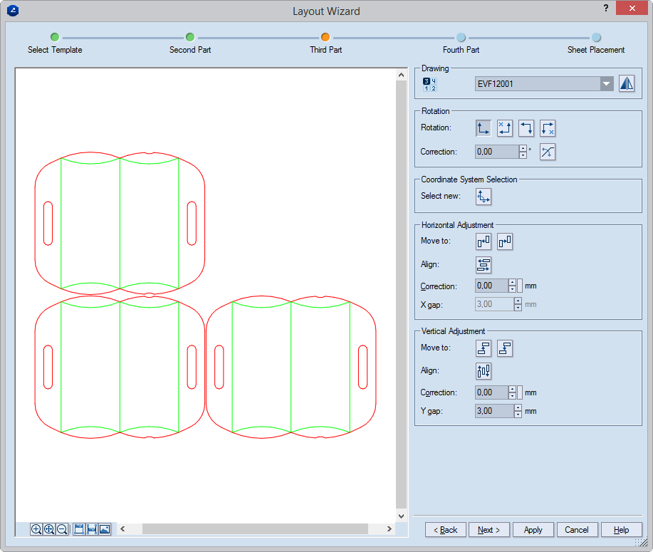
Rotation Options for how the layout 1ups are to be rotated if rotation is needed. The chosen setting applies to all the steps in the wizard.
NOTE: If a predefined templates has been selected in Predefined templates, the rotation options are unavailable, because a rotation pattern has already been defined in the template.
Drawing A list of the drawings in the project that can be set as layout 1ups (parts). Select the drawing that you want to work with. To choose the best case, consider the following notes:
Layout from a project with a single 1up drawing When your project has only one 1up drawing, the drawing's name appears here and you proceed with creating the layout.
Layout from a project with multiple 1up drawings When your project has more than one 1up drawing, you have two scenarios:
The project has its own layout template. The name of the template appears in Predefined Template and the 1up drawings involved in the template appear in the two Drawing area fields. You can create the layout using the predefined template or you can use a different template by selecting it in Predefined Template.
The project does not have its own layout template. You can have two scenarios:
Flip layout 1up  Mirrors
the layout 1up around its vertical axis. The flipping offers one more
choice for arranging the array.
Mirrors
the layout 1up around its vertical axis. The flipping offers one more
choice for arranging the array.
NOTE: The flipping takes place only in the layout array; the position of the original 1up does not change. When you have used this functionality, in the resultant layout array you see a warning in the drawing icon (in the upper left corner of the graphical area), alerting you about the use of at least one flipped 1up.
 Rotation: Rotates the layout 1up by 0 (default),
90, 180, or 270 degrees, respectively.
Rotation: Rotates the layout 1up by 0 (default),
90, 180, or 270 degrees, respectively.
Correction Sets an angle at which the layout 1up will be rotated relative to the current coordinate system. The angle cannot be greater than 45 degrees.
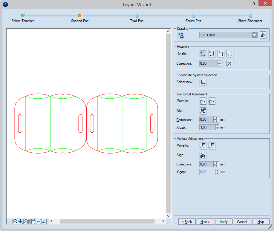
Drawing Lists the available 1ups in the current project which can be used as layout 1ups.
Flip layout 1up Mirrors
the layout 1up around its vertical axis. The flipping offers one more
choice for arranging the array.
NOTE: The flipping takes place only in the layout array; the position of the original 1up does not change. When you have used this functionality, in the resultant layout array you see a warning in the drawing icon (in the upper left corner of the graphical area), alerting you about the use of at least one flipped 1up.
Rotation Options for rotating the layout 1up if rotation is needed.
Rotation Rotates the active layout 1up by 0 (default), 90, 180, or 270 degrees.
NOTE: The x-marked options indicate the rotations that will prevent the correct arraying of the layout 1ups.
Correction Sets an angle at which the layout 1up will be rotated relative to the current coordinate system. The angle cannot be greater than 45 degrees.
 Align part rotation Turns on the mode
that makes parallel two specific objects in different layout 1ups. This
mode is useful when you need that two specific objects be parallel. As
a result, the entire active layout 1up is rotated. To do the alignment,
(1) click the button, (2) click the object from the active layout 1up
that you want to align (make parallel) to another, and then (3) click
the respective object in another layout 1up. As a result, the entire part
is rotated.
Align part rotation Turns on the mode
that makes parallel two specific objects in different layout 1ups. This
mode is useful when you need that two specific objects be parallel. As
a result, the entire active layout 1up is rotated. To do the alignment,
(1) click the button, (2) click the object from the active layout 1up
that you want to align (make parallel) to another, and then (3) click
the respective object in another layout 1up. As a result, the entire part
is rotated.
NOTES:
Coordinate System Selection Clicking the button turns on the mode that sets a new coordinate system for the active layout 1up relative to a specific object in a different layout 1up.
 Select new Turns on the setting of
a new coordinate system for the active layout 1up. Learn
more about how to use this functionality.
Select new Turns on the setting of
a new coordinate system for the active layout 1up. Learn
more about how to use this functionality.
Horizontal Adjustment

 Move To
Fits adjacent layout 1ups horizontally. Moves the layout 1up left-, respectively,
rightward until it reaches the first layout 1up to its left, respectively,
right side. Overrides the value in Correction; the ones in X
Gap is applied.
Move To
Fits adjacent layout 1ups horizontally. Moves the layout 1up left-, respectively,
rightward until it reaches the first layout 1up to its left, respectively,
right side. Overrides the value in Correction; the ones in X
Gap is applied.
 Align Turns on the mode for
horizontal alignment of objects. The layout 1up can be aligned relative
to one of three possible reference objects. Learn
how to use this type of alignment.
Align Turns on the mode for
horizontal alignment of objects. The layout 1up can be aligned relative
to one of three possible reference objects. Learn
how to use this type of alignment.
Correction Sets the horizontal distance correction between the two columns in the array.
NOTE: The arrows on the right-hand side of Correction increase/decrease the value in the box by a default step of 10.00 units. To change the step, click the small rectangular button next to the arrows, and then, in the dialog box that appears, enter a new step.
X Gap Sets the minimal technological horizontal distance along the x-axis between the layout 1ups. The value is applied even when you use the Move To buttons.
Vertical Adjustment

 Move To Fits adjacent layout 1ups vertically. Moves the layout
1up up-, respectively, downward until it reaches the first layout 1up
to its upper, respectively, bottom side. Overrides the value in Correction.
Move To Fits adjacent layout 1ups vertically. Moves the layout
1up up-, respectively, downward until it reaches the first layout 1up
to its upper, respectively, bottom side. Overrides the value in Correction.
 Align Turns on the mode for vertical alignment
of objects. The layout 1up can be aligned relative to one of three possible
reference objects. Learn how to use this
type of alignment. NOTE: The example shows how 1ups are aligned horizontally.
The method for vertical alignment is analogous to it.
Align Turns on the mode for vertical alignment
of objects. The layout 1up can be aligned relative to one of three possible
reference objects. Learn how to use this
type of alignment. NOTE: The example shows how 1ups are aligned horizontally.
The method for vertical alignment is analogous to it.
Correction Sets the vertical distance correction between the two columns in the array. The value is overridden if the Move To buttons are applied.
NOTE: The arrows on the right-hand side of Correction increase/decrease the value in the box by a default step of 10.00 units. To change the step, click the small rectangular button next to the arrows, and then, in the dialog box that appears, enter a new step.
Y Gap Unavailable, since on this wizard page you place no parts that may be set at a distance along the y-axis.
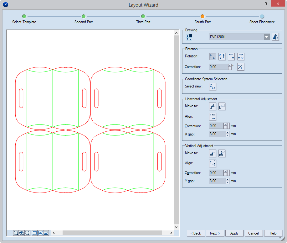
Drawing Lists the available 1ups in the current project which can be used as layout 1ups.
Flip layout 1up Mirrors
the layout 1up around its vertical axis. The flipping offers one more
choice for arranging the array.
NOTE: The flipping takes place only in the layout array; the position of the original 1up does not change. When you have used this functionality, in the resultant layout array you see a warning in the drawing icon (in the upper left corner of the graphical area), alerting you about the use of at least one flipped 1up.
Rotation Options for rotating the layout 1up if rotation is needed.
Rotation Rotates the active layout 1up by 0 (default), 90, 180, or 270 degrees.
NOTE: The x-marked options indicate the rotations that will prevent the correct arraying of the layout 1ups.
Correction Sets an angle at which the layout 1up will be rotated relative to the current coordinate system. The angle cannot be greater than 45 degrees.
Align part rotation Turns on the mode
that makes parallel two specific objects in different layout 1ups. This
mode is useful when you need that two specific objects be parallel. As
a result, the entire active layout 1up is rotated. To do the alignment,
(1) click the button, (2) click the object from the active layout 1up
that you want to align (make parallel) to another, and then (3) click
the respective object in another layout 1up. As a result, the entire part
is rotated.
NOTES:
Coordinate System Selection Clicking the button turns on the mode that sets a new coordinate system for the active layout 1up relative to a specific object in a different layout 1up.
Select new Turns on the setting of
a new coordinate system for the active layout 1up. Learn
more about how to use this functionality.
Horizontal Adjustment
Move To
Fits adjacent layout 1ups horizontally. Moves the layout 1up left-, respectively,
rightward until it reaches the first layout 1up to its left, respectively,
right side.
Align Turns on the mode for
horizontal alignment of objects. The layout 1up can be aligned relative
to one of three possible reference objects. Learn
how to use this type of alignment.
Correction Sets the horizontal distance correction between the two columns in the array.
NOTE: The arrows on the right-hand side of Correction increase/decrease the value in the box by a default step of 10.00 units. To change the step, click the small rectangular button next to the arrows, and then, in the dialog box that appears, enter a new step.
X Gap Unavailable, since on this wizard page you place no parts that may be set at a distance along the x-axis.
Vertical Adjustment
Move To
Fits adjacent layout 1ups vertically. Moves the layout 1up up-, respectively,
downward until it reaches the first layout 1up to its upper, respectively,
bottom side. Overrides the value in Correction applying the ne
in Y Gap.
Align Turns on the mode for vertical
alignment of objects. The layout 1up can be aligned relative to one of
three possible reference objects. Learn
how to use this type of alignment.
NOTE: The example shows how 1ups are aligned horizontally. The method for vertical alignment is analogous to it.
Correction Sets the vertical distance correction between the two columns in the array. The value is overridden if the Move To buttons are applied.
NOTE: The arrows on the right-hand side of Correction increase/decrease the value in the box by a default step of 10.00 units. To change the step, click the small rectangular button next to the arrows, and then, in the dialog box that appears, enter a new step.
Y Gap Sets the minimal technological vertical distance along the y-axis between the layout 1ups. The value overrides the use of the Move To buttons.
Drawing Lists the available 1ups in the current project which can be used as layout 1ups.
Flip layout 1up Mirrors
the layout 1up around its vertical axis. The flipping offers one more
choice for arranging the array.
NOTE: The flipping takes place only in the layout array; the position of the original 1up does not change. When you have used this functionality, in the resultant layout array you see a warning in the drawing icon (in the upper left corner of the graphical area), alerting you about the use of at least one flipped 1up.
Rotation Options for rotating the layout 1up if rotation is needed.
Rotation Rotates the active layout 1up by 0 (default), 90, 180, or 270 degrees.
NOTE: The x-marked options indicate the rotations that will prevent the correct arraying of the layout 1ups.
Correction Sets an angle at which the layout 1up will be rotated relative to the current coordinate system. The angle cannot be greater than 45 degrees.
Align part rotation Turns on the mode
that makes parallel two specific objects in different layout 1ups. This
mode is useful when you need that two specific objects be parallel. As
a result, the entire active layout 1up is rotated. To do the alignment,
(1) click the button, (2) click the object from the active layout 1up
that you want to align (make parallel) to another, and then (3) click
the respective object in another layout 1up. As a result, the entire part
is rotated.
NOTES:
Coordinate System Selection Clicking the button turns on the mode that sets a new coordinate system for the active layout 1up relative to a specific object in a different layout 1up.
Select new Turns on the setting of
a new coordinate system for the active layout 1up. Learn
more about how to use this functionality.
Horizontal Adjustment
Move To
Fits adjacent layout 1ups horizontally. Moves the layout 1up left-, respectively,
rightward until it reaches the first layout 1up to its left, respectively,
right side. Overrides the value in Correction and applies the one
in X Gap.
Align Turns on the mode for
horizontal alignment of objects. The layout 1up can be aligned relative
to one of three possible reference objects. Learn
how to use this type of alignment.
Correction Sets the horizontal distance correction between the two columns in the array.
NOTE: The arrows on the right-hand side of Correction increase/decrease the value in the box by a default step of 10.00 units. To change the step, click the small rectangular button next to the arrows, and then, in the dialog box that appears, enter a new step.
X Gap Sets the minimal technological horizontal distance along the x-axis between the layout 1ups. The value overrides the use of the Move To buttons.
Vertical Adjustment
Move To
Fits adjacent layout 1ups vertically. Moves the layout 1up up-, respectively,
downward until it reaches the first layout 1up to its upper, respectively,
bottom side. Overrides the value in Correction and applies the
one in Y Gap.
Align Turns on the mode for vertical
alignment of objects. The layout 1up can be aligned relative to one of
three possible reference objects. Learn
how to use this type of alignment.
NOTE: The example shows how 1ups are aligned horizontally. The method for vertical alignment is analogous to it.
Correction Sets the vertical distance correction between the two columns in the array. The value is overridden if the Move To buttons are applied.
NOTE: The arrows on the right-hand side of Correction increase/decrease the value in the box by a default step of 10.00 units. To change the step, click the small rectangular button next to the arrows, and then, in the dialog box that appears, enter a new step.
Y Gap Sets the minimal technological horizontal distance along the y-axis between the layout 1ups. The value overrides the use of the Move To buttons.
The Sheet Placement step appears.
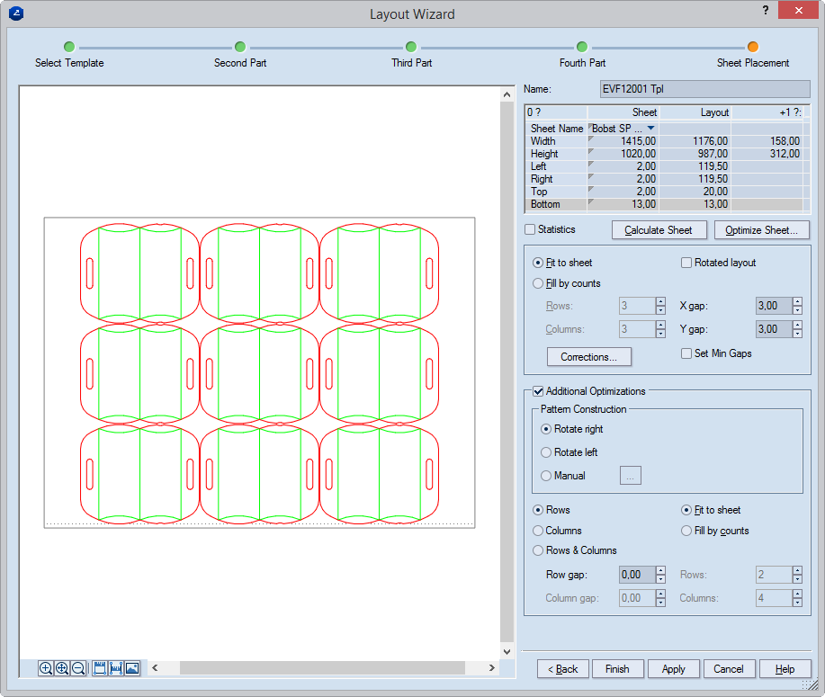
The table
The Sheetcolumn Sets the sheet in the layout:
Click the right end of the Sheet Name field to see a list of predefined standard sheet formats. If you do not want to use any of the standard sheet sizes, select User-defined.
(Optional) Correct the sheet width in the Width field.
(Optional) Correct the sheet height in the Height field.
(Optional) Correct the sheet margins in the Bottom, Left, Top and Right fields.
The Layoutcolumn: Displays statistics about the layout width, height and margins.
The +1? column: Displays information about the minimal distance that must be added to the sheet's width or height in the table if one more column or, respectively, row is needed in the layout. Only data for the width and height is displayed in this column. The values change if the Rotated layout check box is selected, reflecting the state of the layout when it has been rotated.
Statistics Selecting the check box toggles the view in the table, displaying additional information about the layout for straight and rotated layout. Depending on whether the Rotated layout check box is selected, the Straight or Rotated column in the table shows its data in bold, indicating the selected layout arrangement.
Calculate Sheet Calculates the layout by applying a sheet size into which the currently defined layout fits fully.
Optimize Sheet Launches a mode in which the sheet optimization.
Fit to sheet* Fits the sheet by automatically calculating the number of rows and columns that can be placed onto the sheet. If the sheet is too small for the number of rows and columns as set in Rows and Columns, the extra rows/columns are trimmed. Respectively, if the sheet can take in more rows and/or columns than are set, their number is added to the layout until the sheet is fully used.
Fill by counts* Adds more rows and/or columns to the sheet. If the sheet is too small for the number of the set rows and columns, they are represented as sticking out of the sheet. In this case, in the table enter new values for Width and Height of the Sheet column or use the Opt Sheet button to calculate a new sheet.
TIP: You can use the data in the +1? column as a hint on what new value to enter.
Rotated layout Rotates the layout at 90 degrees counterclockwise, offering an alternative array. Selecting this check box affects the view in the table (see the descriptions for the Statistics check box) and that for the +1? column (see its description above). When the Statistics check box is selected, in the table, the statistics for the straight and the rotated layout are displayed, with the current one in bold type.
Rows Sets how many rows the layout is to have.
Columns Sets how many columns the layout is to have.
X gap Sets a horizontal distance correction between the objects in the layout.
Y gap Sets a vertical distance correction between the objects in the layout.
Corrections Opens the dialog box in which you can make additional arrangement of the 2nd column and the 2nd row.
Set Min Gaps Fixes the values you have entered in X Gap and Y Gap as minimal gap values for the layout template.
HOW TO USE MINIMAL GAPS:
Additional Optimizations Displays additional optimization settings for the original layout pattern; for better layout disposition, you can define an additional layout pattern. Such a pattern is every modification of the original layout pattern — for example, rotated original layout pattern or one containing different designs.
Pattern Construction Settings for the definition of an additional layout pattern.
Rotate right Rotates the layout pattern to the right, generating an optimal layout output.
Rotate left Rotates the layout pattern to the left, generating an optimal layout output.
Manual Opens a wizard in which you can set a different template or define a new one.
Rows Adds rows to the additional layout pattern.
NOTE: Selecting the check box enables the Row gap box, in which you can set a distance between the rows.
Columns Adds columns to the additional layout pattern.
NOTE: Selecting the check box enables the Column gap box, in which you can set a distance between the columns.
Rows & Columns Adds both rows and columns to the additional layout pattern.
NOTE: Selecting the check box enables the Column gap and Row gap boxes, in which you can set distances between, respectively, the columns and rows.
Row gap Sets a gap between the rows of the original layout and the additional layout patterns.
Column gap Sets a gap between the columns of the original layout and the additional layout patterns.
* The following situations may occur when the Fit to sheet and Fill by counts options are used for both the original pattern and the additional optimizations:
Fit to sheet chosen for both the original pattern and the additional optimizations. The optimum number of designs to be placed on the sheet is calculated, regardless of whether the designs come from the original or the additional layout pattern.
Fill by counts chosen for both the original pattern and the additional optimizations. First the original layout fits the selected/user-defined sheet according to the values defined for Rows and Columns, and then the fitting of the additional layout follows. If the sheet is too small for the number of rows and columns you set at the moment, they are not trimmed, but appear as projecting out of the sheet.
Fill by counts chosen for the original pattern and Fill by counts chosen for additional optimizations. First the original pattern fits the selected/user-defined sheet according to the values defined for Rows and Columns, followed by the fitting of the additional layout if there is enough space within. If the sheet is too small for the number of rows and columns you set at the moment, they are not trimmed, but appear as projecting out of the sheet; the additional layout is not placed.
Fill by counts chosen for the original one and Fill by counts chosen for the additional optimizations. First the additional layout fits the selected/user-defined sheet according to the values defined for Rows and Columns, followed by the fitting of the original layout if there is enough space within. If the sheet is too small for the number of rows and columns you set at the moment, they are not trimmed, but appear as projecting out of the sheet; the original design is not placed.
The Layout: Align 2-nd column and row dialog box appears.
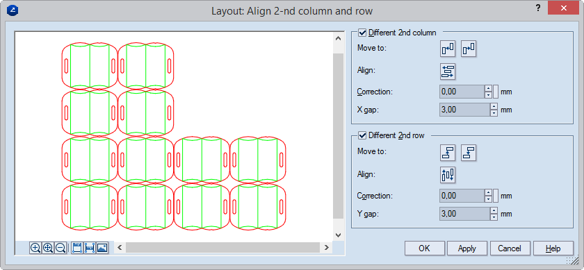
Different 2nd column The second column in the initial '2 rows by 2 columns' array is treated as different from the first one. If the columns in the layout are more than two, every even-numbered column is treated as second, arranging the columns in exactly the same pattern set for the first '2 rows by 2 columns' array in the previous wizard steps. Selected automatically if the second column in the layout is naturally different from the first as a result of previous corrections in the wizard — for example, different arrangement, different part type, or other modifications.
Move To Attaches neighboring layout 1ups.
NOTE: Moving layout 1ups overrides the value in Correction, applying the one in X Gap.
Move Left Moves the current layout
1up leftward until it is attached to the first adjacent part on its left
side without overlapping it. The layout 1up does not move if there is
no object in the leftward path of the layout 1up.
Move Right Moves the current layout
1up rightward until it is attached to the first adjacent part on its right
side without overlapping it. The layout 1up does not move if there is
no object in the downward path of the layout 1up.
Align Turns on the mode for horizontal
alignment of objects. The layout 1up can be aligned in reference to one
of three possible reference objects. Learn
how to use this type of alignment.
Align Turns on the mode for vertical
alignment of objects. The layout 1up can be aligned in reference to one
of three possible reference objects. Learn
how to use this type of alignment.
Correction Sets the horizontal distance correction between the two columns in the array.
X Gap Sets the minimal horizontal distance along the x-axis between the layout 1ups. Sets the horizontal distance correction between the two columns in the array.
Different 2nd row The second row in the initial '2 rows by 2 columns' array is treated as different from the first one. If the rows in the layout are more than two, every even-numbered row is treated as second, and the rows are arranged in the same pattern as the one was set for the first '2 rows by 2 columns' array in the previous wizard steps. Selected automatically if the second row in the layout is different from the first one as a result of previous corrections made in the wizard — for example, different arrangement, different part type, or other modifications.
Move To Attaches adjacent layout 1ups.
NOTE: Moving layout 1ups overrides the value in Correction, applying the one in Y Gap.
Align Turns on the mode for vertical
alignment of objects. The layout 1up can be aligned in reference to one
of three possible reference objects. Learn
how to use this type of alignment.
Move Up Moves the current layout
1up upward until it is attached to the first adjacent layout 1up above
it without overlapping it. If there is no object in its upward path, the
layout 1up does not move.
Move Down Moves the current layout
1up downward until it is attached to the first adjacent layout 1up under
it without overlapping it. If there is no object in its downward path,
the layout 1up does not move.
Align Turns on the mode for vertical
alignment of objects. The layout 1up can be aligned in reference to one
of three possible reference objects. Learn
how to use this type of alignment.
NOTE: The example shows how 1ups are aligned horizontally. The method for vertical alignment is analogous to it.
Correction Sets the horizontal distance correction between the two rows in the array.
Y Gap Sets the minimal horizontal distance along the y-axis between the layout 1ups. Sets the vertical distance correction between the two rows in the array.